John III Beumer - Fundamentals of Implant Dentistry
Здесь есть возможность читать онлайн «John III Beumer - Fundamentals of Implant Dentistry» — ознакомительный отрывок электронной книги совершенно бесплатно, а после прочтения отрывка купить полную версию. В некоторых случаях можно слушать аудио, скачать через торрент в формате fb2 и присутствует краткое содержание. Жанр: unrecognised, на английском языке. Описание произведения, (предисловие) а так же отзывы посетителей доступны на портале библиотеки ЛибКат.
- Название:Fundamentals of Implant Dentistry
- Автор:
- Жанр:
- Год:неизвестен
- ISBN:нет данных
- Рейтинг книги:5 / 5. Голосов: 1
-
Избранное:Добавить в избранное
- Отзывы:
-
Ваша оценка:
Fundamentals of Implant Dentistry: краткое содержание, описание и аннотация
Предлагаем к чтению аннотацию, описание, краткое содержание или предисловие (зависит от того, что написал сам автор книги «Fundamentals of Implant Dentistry»). Если вы не нашли необходимую информацию о книге — напишите в комментариях, мы постараемся отыскать её.
Fundamentals of Implant Dentistry — читать онлайн ознакомительный отрывок
Ниже представлен текст книги, разбитый по страницам. Система сохранения места последней прочитанной страницы, позволяет с удобством читать онлайн бесплатно книгу «Fundamentals of Implant Dentistry», без необходимости каждый раз заново искать на чём Вы остановились. Поставьте закладку, и сможете в любой момент перейти на страницу, на которой закончили чтение.
Интервал:
Закладка:
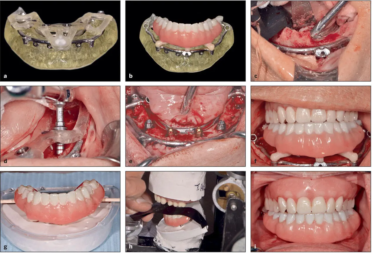
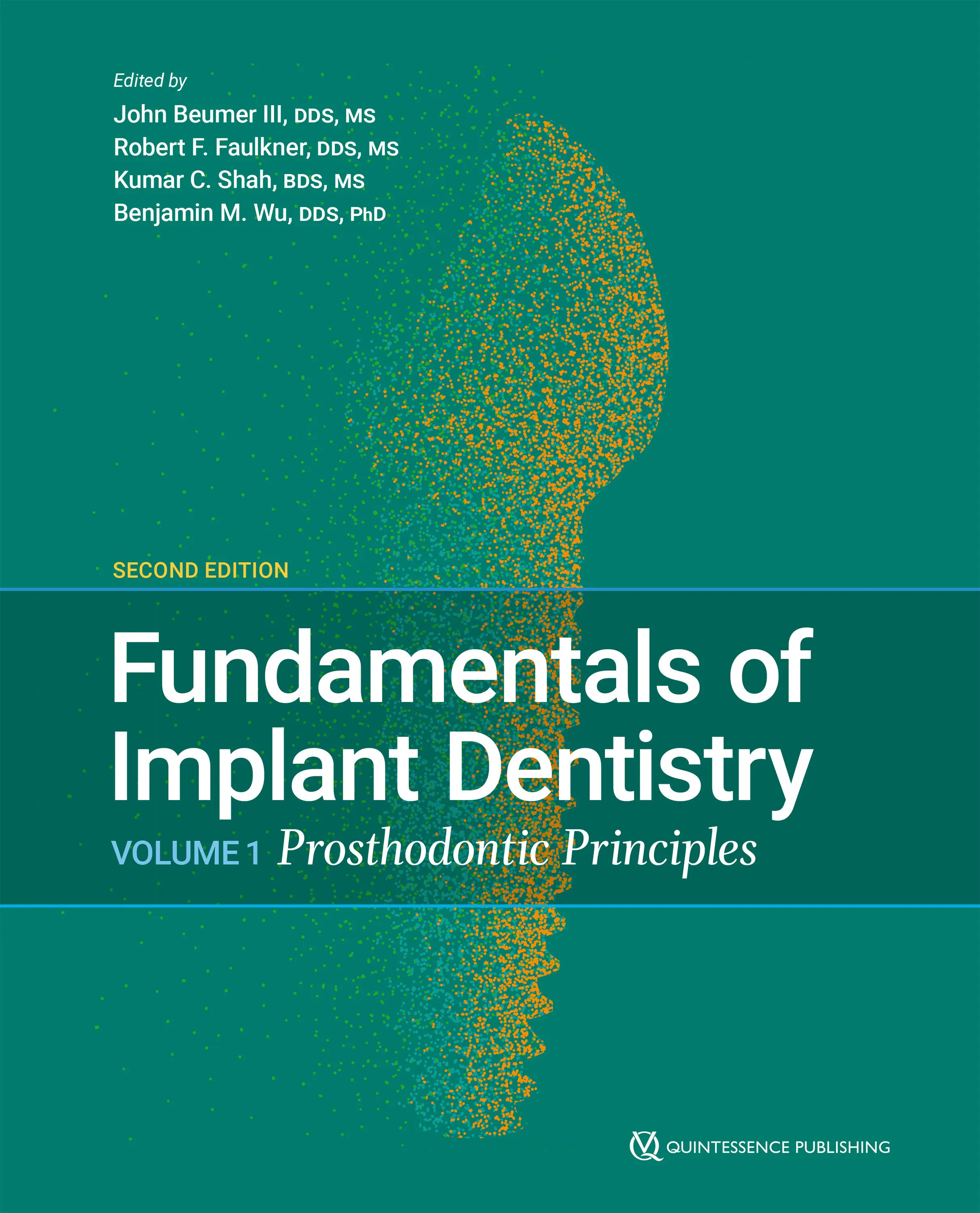
Fig 5-15 Digital planning enables presurgical selection of abutments and permits fabrication of an immediate load conversion prosthesis. (a) “Stacked” surgical guides on a printed bone model. (b) The immediate load prosthesis is keyed to the foundation template. (c) The foundation template is secured with bone screws and also serves as a bone reduction guide. (d) The osteotomy sites are prepared, and the implants are inserted. The drills are designed with shanks that precisely engage the drill sleeves (bushings). (e) Abutments have been secured to the implants. The precision achieved with digital workup and fully guided surgery permits selection of the angled abutments prior to surgery. (f) The immediate load prosthesis keyed to the foundation template and ready to be secured to the abutment cylinders. (g) Remount cast of the final conversion interim prosthesis. (h) Clinical remount to ensure proper occlusal contacts in centric relation position. (i) Prosthesis fixated demonstrating desired occlusal contacts.
Computer-planned and guided implant surgery
From its inception, implant dentistry was driven primarily by the surgical discipline. Before surgical guides, freehand surgery was the primary method by which implants were placed, and this method was largely dependent on the surgeon’s experience and knowledge of the prosthodontic principles related to implant surgery. This led to implants being placed into bone but not necessarily in positions that were optimal for the prosthetic design. 98Eventually, the importance of having a prosthetic plan prior to implant placement gained acceptance. Today, it is generally regarded that implants should be placed according to the prosthetic design. 99
As a consequence, surgical guides to control implant positioning have proven to be useful devices when performing implant surgery by relating the implant position to the specific prosthodontic plan of treatment. Traditionally, surgical guides were produced by the laboratory according to the diagnostic wax-up. 100As several aspects of digital technology continue to evolve with respect to implant dentistry, one of the more remarkable advances is the ability to plan implant surgeries from both the prosthetic and surgical perspectives, allowing the implants to be strictly placed via accurate surgical guides. The final prosthesis can be virtually designed according to the intraoral features and available bone observed from the CBCT image, making it possible to plan for the most ideal implant to achieve the planned prosthesis.
The design process begins by merging the STL files obtained from the diagnostic casts, diagnostic wax-up/setup, or existing prostheses with the Digital Imaging and Communications in Medicine (DICOM) data produced from the CBCT scan into a computer software program. The merging process is very reliable, because it utilizes the teeth as common landmarks between the STL files and the 3D image. Eventually, the relationship between the intraoral tissues and the underlying alveolar bone can be reliably viewed. For edentulous patients, a dual-scan technique is implemented. An acceptable denture or denture setup with the correct fit and tooth position is used as radiographic template. It can be modified by placing six to eight fiducial radiopaque markers (eg, gutta-percha or DentalMark products [Suremark]) on both the buccal and lingual denture base areas in a staggered fashion ( Fig 5-16). A CBCT scan or surface scan of the radiographic template (denture or denture setup) is then obtained separately, followed by a CBCT scan of the patient with the radiographic template in place. Care should be taken to ensure that the fiducial markers remain in the same position as initially scanned. These two scans are then merged together to outline the clear relationship between the alveolar bone and the planned prosthetic design. 101
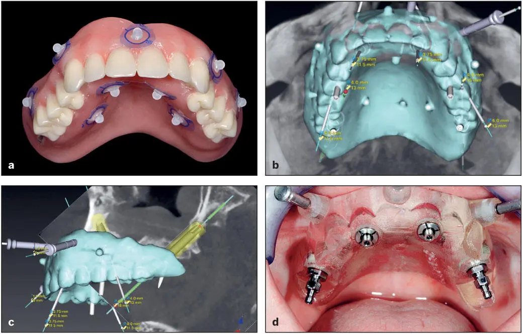
Fig 5-16 Guided implant surgery planning. (a) Denture with acceptable tooth positions with the fiducial radiopaque markers. (b and c) CBCT scan images superimposed with denture scan using dual-scan protocol such that implant position planning can be initiated. (d) Guide in place fixated with anchor pins and implants placed.
Once the images are visualized in 2D sections and 3D, the implants are virtually placed according to the prosthodontic requirements of the intended prosthesis and the anatomical limitations of the patient. If anatomical limitations exist that prohibit ideal implant placement, then a determination must be made as to the necessity for altering implant position or deciding on augmentation procedures prior to implant placement. In addition, the effect of any alteration in the implant position on prosthesis design can easily be visualized. Once the implant length, diameter, depth, and angulation are determined, the surgical guide is designed to reflect these parameters. Some softwares have the ability to add the prosthetic abutment design at this point. This is particularly useful in planning for angulated prefabricated abutments for multiple units with a full-arch prosthesis. The guide design should allow for soft tissue manipulations without interfering with the positioning of the guide. Once the guide design is verified, it is produced by 3D printing or milling. Metal sleeves that are calibrated to a specific implant system’s guided drills and kits are attached for either fully guided or semiguided surgery. The software can then generate the detailed procedure protocol to be followed closely intraoperatively ( Fig 5-17).
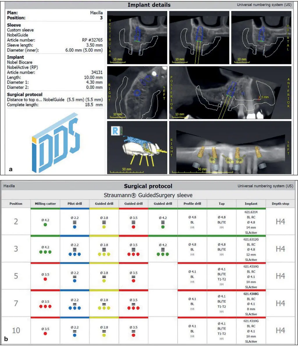
Fig 5-17 An example of the guided implant surgery. (a) Details of the planned implants. (b) Surgical protocol for the drill sequence and steps to be followed intraoperatively.
Depending on the seating of the surgical guides, three basic designs are available: (1) tooth-borne, (2) bone-borne, or (3) soft tissue–borne. 102In some cases, a combination of these designs can be considered. When treating a partially edentulous patient, the surgical guide is typically tooth borne ( Fig 5-18); however, a combination of tooth- and tissue-borne or tooth- and bone-borne can be considered for large edentulous segments. The friction between the teeth and the guides will stabilize them during surgery. Visual access windows can be incorporated within the guide to ensure proper seating on the teeth.
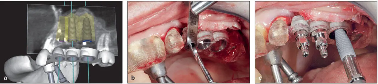
Fig 5-18 A tooth-borne surgical guide designed for fully guided surgery. (a) Virtually planned implant positions and surgical guide designed. (b) Use of a drill key (arrow) that seats into the drill sleeves (bushings). These drill keys conform to the implant drill dimensions. (c) Implant placement through the surgical guide. (Reprinted from Moy et al 23with permission.)
For the edentulous patient, the guides can rest on the mucosa (see Fig 5-16d) or directly on bone (see Figs 5-12and 5-15). For stability, these guides can be fixed by lateral/anchor pins/screws to the bone. The level of fit of the guide is thought to influence the accuracy of implant placement in relation to implant planning. The tooth-borne guides are generally more accurate, 103as they are fabricated on an STL of the teeth (see Fig 5-18). The soft tissue–borne guides are based on STL images of the patient’s ridge. However, the compressibility of the tissues may cause some deviation from the planned implant site. The bone-borne guides are purely based on CBCT DICOM data, which are not as accurate as STL images of the intraoral tissues that are produced by a digital impression or a conventional impression followed by a laboratory scanner. This may explain the inferior accuracy reported for the bone-borne guides. However, bone-borne guides have the advantage of surgical visibility during drilling and implant placement. Normally, bone-borne guides are used for patients in need for adjunctive bone reduction during implant placement. 102However, these guides require a larger reflection of the flap to ensure complete seating on bone.
Читать дальшеИнтервал:
Закладка:
Похожие книги на «Fundamentals of Implant Dentistry»
Представляем Вашему вниманию похожие книги на «Fundamentals of Implant Dentistry» списком для выбора. Мы отобрали схожую по названию и смыслу литературу в надежде предоставить читателям больше вариантов отыскать новые, интересные, ещё непрочитанные произведения.


Обсуждение, отзывы о книге «Fundamentals of Implant Dentistry» и просто собственные мнения читателей. Оставьте ваши комментарии, напишите, что Вы думаете о произведении, его смысле или главных героях. Укажите что конкретно понравилось, а что нет, и почему Вы так считаете.