Rethinking Prototyping
Здесь есть возможность читать онлайн «Rethinking Prototyping» — ознакомительный отрывок электронной книги совершенно бесплатно, а после прочтения отрывка купить полную версию. В некоторых случаях можно слушать аудио, скачать через торрент в формате fb2 и присутствует краткое содержание. Жанр: unrecognised, на английском языке. Описание произведения, (предисловие) а так же отзывы посетителей доступны на портале библиотеки ЛибКат.
- Название:Rethinking Prototyping
- Автор:
- Жанр:
- Год:неизвестен
- ISBN:нет данных
- Рейтинг книги:3 / 5. Голосов: 1
-
Избранное:Добавить в избранное
- Отзывы:
-
Ваша оценка:
Rethinking Prototyping: краткое содержание, описание и аннотация
Предлагаем к чтению аннотацию, описание, краткое содержание или предисловие (зависит от того, что написал сам автор книги «Rethinking Prototyping»). Если вы не нашли необходимую информацию о книге — напишите в комментариях, мы постараемся отыскать её.
The Design Modelling Symposium Berlin 2013 would like to challenge the participants to reflect on the possibility of computational systems that bridge design phase and occupancy of buildings. This rethinking of the designed artifact beyond its physical has had profound effects on other industries already. How does it affect architecture and engineering?
At the scale of engineering and building systems new perspectives may open up by engaging built form as a continuous prototype, which can track and respond during use and serve as a real world implementation of its design model. This has been tried many times from intelligent façades to smart homes and networked grids but much of it was only technology driven and not approached from a more holistic design perspective.
Rethinking Prototyping — читать онлайн ознакомительный отрывок
Ниже представлен текст книги, разбитый по страницам. Система сохранения места последней прочитанной страницы, позволяет с удобством читать онлайн бесплатно книгу «Rethinking Prototyping», без необходимости каждый раз заново искать на чём Вы остановились. Поставьте закладку, и сможете в любой момент перейти на страницу, на которой закончили чтение.
Интервал:
Закладка:
Fig. 2 (a) Luigi Nervi, Palazzo del Lavoro (1961) (Photograph: Roberto Saba) (b) Frank Lloyd Wright, Johnson Wax Building (1936) (Photograph: Jack Boucher)
Nevertheless, these structures (Figs. 1-2) and numerous other examples from medieval times (Fig. 3a) show the potential of architectural applications and spatial configurations using funnel geometry (Clifford 2012). However, up to now, the structural potential of this building typology has not been fully exploited in order to extend its architectural vocabulary.
1.2 Structural Potential of Funicular Funnel-Shaped Shells
The structural efficiency of shells comes from the fact that their dominated load-bearing is membrane action, i.e. axial compressive or tensile force flows along its centre surface, which is inherently more efficient than carrying loads through bending.
Traditional vault construction demonstrates the use of efficient structural form in combination with funnel-shaped architecture, such as the rib vault of the chapel of Cluny Museum in Paris, France (1485-1510). This masonry vault of course stands efficiently in compression due to its funicular shape (Fig. 3a) resulting in a relatively filigree structure. The contemporary installation La Voûte de LeFevre (2012) by Matter Design is based on the same structural system, featuring a more irregular geometry thanks to digital, structural form finding and CNC fabrication (Fig. 3b).
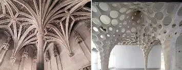
Fig. 3 (a) Rib vault of the chapel of Cluny Museum (1485-1510); (b) Matter Design, La Voûte de LeFevre (2012)
Yet, these compression structures depend on fixed boundary conditions, which usually do not allow opening up the sides. The vaults in Fig. 3a are stable thanks to massive buttresses taking the horizontal thrust of the rib structure. The openness and lightness of the installation in Fig. 3b on the other hand can only be achieved by a steel frame suspended from the ceiling of the gallery space. The structure thus depends on this continues support, in contrast to the cantilevering structures in Fig. 2. The question arises how one can use the structural efficiency of funicular shapes to create open, funnel-shaped shells without the need of a secondary structural frame acting in bending or heavy buttresses.
This paper discusses a direct form-finding approach for funicular funnel shells, and demonstrates the manifold design space of these structures. In the following section, the basic structural principle is illustrated by referring to traditional and contemporary construction techniques. Subsequently, graphic statics and its extension to surface structures, Thrust Network Analysis, are discussed. In the last section, the form-finding approach and its implementation as a design tool are tested through a digital design exploration, and finally verified using a 3D printed, structural scale model.
2 Structural Principle
The basic structural concept discussed in this paper is based on the use of compression-only vaults in combination with continuous tension ties. This combination is of course known from masonry domes where continues tension rings are often inserted to resist the tensile hoop force towards the supports. Felix Candela used a similar system of combining tension and compression forces for his umbrella shells in the 1950s.
Fig. 4 illustrates the use of partial compression arches balanced by tension ties, showing (a) a barrel vault, and (b) a modern concrete arch bridge, both during the erection stage. Both structures are in static equilibrium thanks to temporarily attached cables which counteract the horizontal thrust until the barrel vault, respectively the arch, is closed. In these two examples the tension tie is used as a restraint during construction. However, this temporary state could also represent the structural system of a finalized structure. Hence, these examples serve as a sketch to illustrate the half-arch tension equilibrium system.
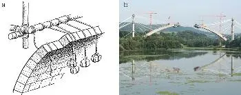
Fig. 4 (a) Medieval vault construction using tensioned ropes (Fitchen 1961); (b) construction of the Froschgrundseebrücke, near Coburg, Germany.
2.1 2D Form-Finding Using Graphic Statics
The examples in Fig. 4 show how funicular structures such as half arches can stand in equilibrium by introducing tension elements. This structural principle to create large cantilevering structures is illustrated in Fig. 5 using simple graphic statics. Graphic statics is based on two diagrams: a form diagram, representing the geometry of the pin-jointed structure, and a force diagram, also referred to as (Maxwell-) Cremona diagram, representing the equilibrium of the internal and external forces of the structure (Cremona 1890). The power of graphic statics is based on its inherent bidirectional capabilities; one can either use the form diagram to construct the force diagram, or apply the inverse process and construct parts of the form diagram from an intended force diagram, i.e. either form or force constraints can drive the design exploration (Kilian 2006). Geometrically, the relation between the form and force diagram is called reciprocal (Maxwell 1864). Graphic statics also allows to mutually use compression and tension elements which can be easily identified based on their individual direction in the form and force diagram.
Fig. 5 shows the form and force diagram of a funicular arch in compression (a) and the same structure cut in half, with one half flipped horizontally (b). The equilibrium of each node in the form diagram is represented by a closed force vector polygon in the force diagram. Note that the upper ends of both arch segments (b) are in static equilibrium considering the appropriate reaction forces. These reaction forces can either be guaranteed by horizontal supports such as buttresses on both sides or by using a tension tie connecting both ends (Fig 5b).
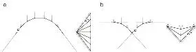
Fig. 5 (a) Form and force diagram of a closed funicular arch in compression; (b) two, tied half arches in static equilibrium (tension forces marked in blue)
2.2 3D Form-Finding Using Extended Thrust Network Analysis
Imagine now that we take several of the tied half arches in Fig. 5b and arrange them in a radial configuration as shown in the equilibrium network G (Fig. 6). Instead of having a tension tie for each pair of aligned arches, this same spatial layout of arches can be balanced by a continuous, polygonal tension ring (Fig. 7). The horizontal equilibrium, and hence the plan geometry, of this funicular tension ring is defined by the (equal) thrusts of the half-arches, and can be represented by the reciprocal force diagram Γ* in Fig. 7.
Such reciprocal diagrams of form and forces are used in Thrust Network Analysis (TNA) (Block & Ochsendorf 2007; Block 2009) to explain and control the horizontal equilibrium of compression-only vaults. To guarantee compression, Block (2009) explains that corresponding directed edges ei and ei* in both diagrams need to have the same directions, i.e. not only be parallel, but furthermore have the same orientation, resulting in positive force densities q, which are the ratios of the corresponding edge lengths of the force diagram Γ and the form diagram Γ*. Tension elements have negative force densities, and their corresponding edges in form and force diagram thus have opposite directions. For two reciprocal diagrams, the sign of axial forces in the elements can thus directly be obtained by using the normalised dot product of the corresponding edges, -1 for tension, and +1 for compression (Eq. 1).
Читать дальшеИнтервал:
Закладка:
Похожие книги на «Rethinking Prototyping»
Представляем Вашему вниманию похожие книги на «Rethinking Prototyping» списком для выбора. Мы отобрали схожую по названию и смыслу литературу в надежде предоставить читателям больше вариантов отыскать новые, интересные, ещё непрочитанные произведения.


Обсуждение, отзывы о книге «Rethinking Prototyping» и просто собственные мнения читателей. Оставьте ваши комментарии, напишите, что Вы думаете о произведении, его смысле или главных героях. Укажите что конкретно понравилось, а что нет, и почему Вы так считаете.