Applications of Polymer Nanofibers
Здесь есть возможность читать онлайн «Applications of Polymer Nanofibers» — ознакомительный отрывок электронной книги совершенно бесплатно, а после прочтения отрывка купить полную версию. В некоторых случаях можно слушать аудио, скачать через торрент в формате fb2 и присутствует краткое содержание. Жанр: unrecognised, на английском языке. Описание произведения, (предисловие) а так же отзывы посетителей доступны на портале библиотеки ЛибКат.
- Название:Applications of Polymer Nanofibers
- Автор:
- Жанр:
- Год:неизвестен
- ISBN:нет данных
- Рейтинг книги:4 / 5. Голосов: 1
-
Избранное:Добавить в избранное
- Отзывы:
-
Ваша оценка:
Applications of Polymer Nanofibers: краткое содержание, описание и аннотация
Предлагаем к чтению аннотацию, описание, краткое содержание или предисловие (зависит от того, что написал сам автор книги «Applications of Polymer Nanofibers»). Если вы не нашли необходимую информацию о книге — напишите в комментариях, мы постараемся отыскать её.
Explore a comprehensive review of the practical experimental and technological details of polymer nanofibers with a leading new resource Applications of Polymer Nanofibers
Applications of Polymer Nanofibers
Applications of Polymer Nanofibers
Applications of Polymer Nanofibers — читать онлайн ознакомительный отрывок
Ниже представлен текст книги, разбитый по страницам. Система сохранения места последней прочитанной страницы, позволяет с удобством читать онлайн бесплатно книгу «Applications of Polymer Nanofibers», без необходимости каждый раз заново искать на чём Вы остановились. Поставьте закладку, и сможете в любой момент перейти на страницу, на которой закончили чтение.
Интервал:
Закладка:
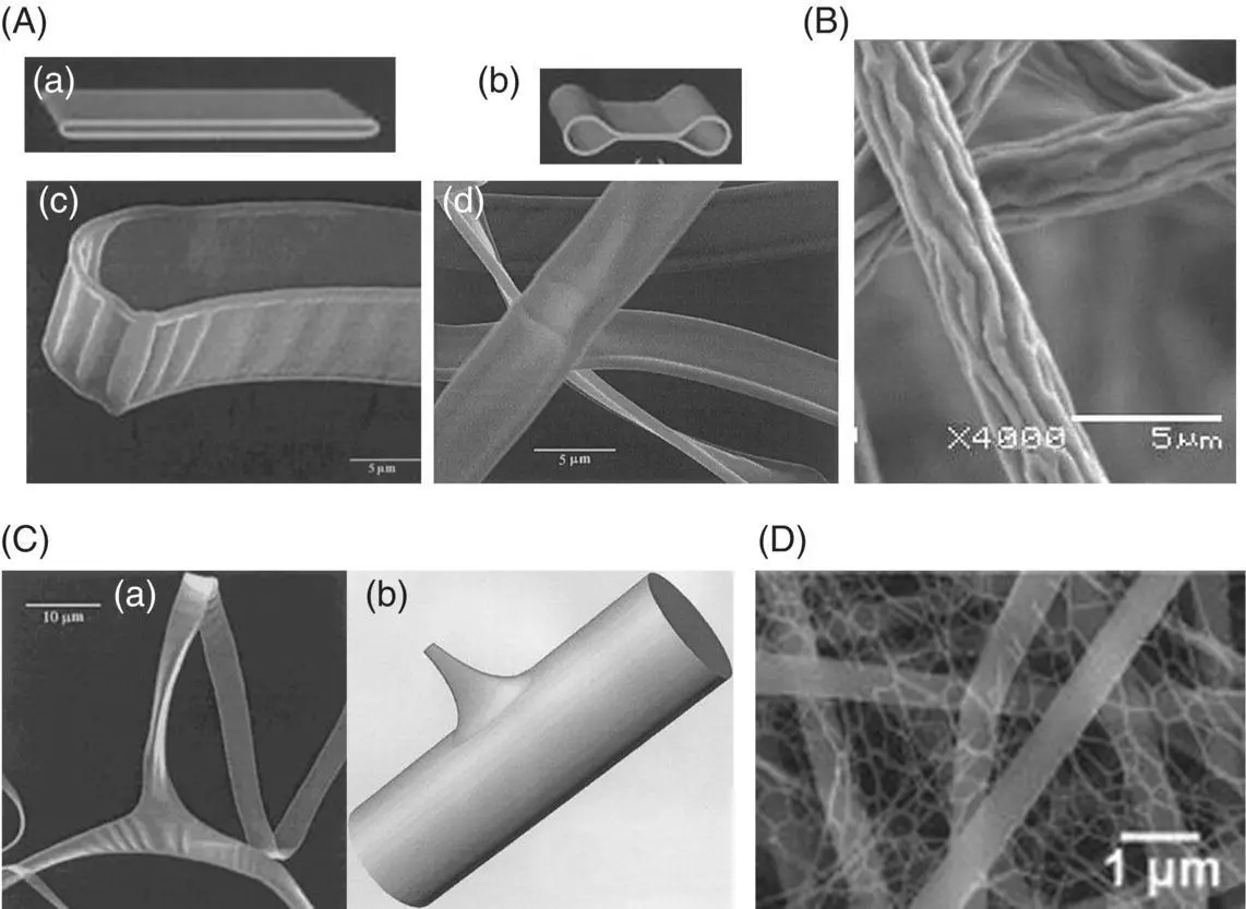
Figure 1.4 Overview of interesting electrospun structures: (A (a–d)) ribbons
( Source: Reprinted from Koombhongse et al. (2001). Copyright (2001). Wiley.),
(B) wrinkled fiber
( Source: Reprinted (adapted) with permission from Pai et al. (2009). Copyright (2009). American Chemical Society.),
(C (a, b)) branched fibers
( Source: Reprinted from Koombhongse et al. (2001). Copyright (2001). Wiley.),
and (D) fiber nets
( Source: Reprinted from Wang et al. (2017). Copyright (2017), with permission from Elsevier.).
Alternatively, when the skin collapses, the fiber surface can wrinkle due to the buckling instability associated with the skin pulling inward as the solvent evaporates. The final shape, i.e. wrinkled fibers or a flat fiber, depends on the ratio of the Young's modulus of the core to that of the shell as well as the ratio of the radius of the fiber to thickness of the shell. The wrinkles are less deep when there are more wrinkles and the cross section is closer to circular. The morphology can also be affected by solvent volatility. Higher volatility tends to result in ribbons, whereas lower volatility tends to lead to wrinkling. For example, polystyrene/tetrahydrofuran (high volatility) formed ribbons, whereas polystyrene/DMF (low volatility) produced wrinkled fibers at the same polymer concentration (Koombhongse et al. 2001; Wang et al. 2009).
Another morphology that can occur in electrospun fibers is branching. Branched fibers are a small fiber splitting from the main fiber, and these splits are often times formed at the bends of the fibers. Similarly, split fibers occur when a primary fiber splits into smaller fibers. This phenomenon is due to jet instability. Nanofiber/net structures have also been reported. Din et al. electrospun a polyvinyl alcohol/H 2O/formic acid mixture and observed typical electrospun nanofibers ~200 nm and a 2D‐nanonet of interconnected nanofibrils with average fiber diameter ~25 nm. This morphology was attributed to the formic acid. The authors posit that the ionized formic acid causes excess charge and a number of charged droplets. Charged droplets form thin films in contact with the liquid jet. Upon solvent evaporation and thermal‐induced phase separation (TIPS) in the thin film, the solidification of the polymer‐rich phase results in a Steiner network of 2D nanonet/nanofibrils. The structure affected transport properties through the electrospun membrane as well as the membrane wettability. Similar structures have been observed with polyamide 6, polyacrylic acid, polyurethane, chitosan, and poly(methyl methacrylate) (Wang et al. 2017).
1.6.2 Porous Fibers
Porous electrospun nanofibers ( Figure 1.5) are of increasing interest in filtration, energy storage, tissue engineering, and catalysis (Li and Xia 2004; Katsogiannis et al. 2016; Wei et al. 2013; Natarajan et al. 2014; Hou et al. 2014). The pores increase surface area of the fibers (Katsogiannis et al. 2016; Natarajan et al. 2014). In tissue engineering, porous scaffolds better mimic extracellular matrix and improve cell attachment (Katsogiannis et al. 2015, 2016).
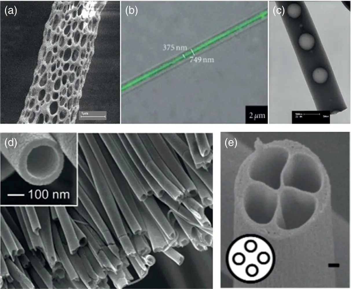
Figure 1.5 Overview of advanced electrospun nanofiber cross sections: (a) porous fibers
( Source: Dayal et al. (2007).),
(b, c) core–shell fibers
( Source: (b) Reprinted from Dicks and Heunis (2010). Copyright (2010). T.D.J. Heunis and L.M.T. Dicks;
(c) Reprinted from Jalaja et al. (2016), Copyright (2015), with permission from Elsevier.),
and (d, e) nanochannels
( Source: Zhao et al. (2007)).
One approach to making porous nanofibers is electrospinning multicomponent fibers and selectively leaching one of the components (Wei et al. 2013; Gupta et al. 2009). For example, polycaprolactone and sodium chloride can be electrospun from a solvent mixture of methanol and chloroform. The subsequent fibers were submerged in water to selectively dissolve the salt to produce porous fibers (Wang et al. 2009). Polymers have also been used as porogens (Wei et al. 2013) and lead to interconnected pores throughout the fiber. Leeching of salt with water is advantageous because it avoids introducing toxic substances into the system (Hou et al. 2014). However, the salt may not be fully mixed resulting in uneven pore sizes and distributions. Further, this method is time‐consuming as complete leeching of the salt can sometimes be difficult (Wei et al. 2013).
Porous fibers can also be achieved during electrospinning by inducing phase separation (Dayal et al. 2007; Dayal and Kyu 2006). Several variations for inducing phase separation have been explored including TIPS/vapor‐induced phase separation (VIPS) in which water condenses on the surface of the fibers as the solvent evaporates and reduces temperature leading to pores (Natarajan et al. 2014), and nonsolvent‐induced phase separation (NIPS) in which solvent mixtures are used to induce phase separation (Dayal and Kyu 2006). In NIPS, a mixture of solvents of varying volatilities is used. In this approach, the electrospinning solution is a stable, one‐phase system. As solvent evaporates and the polymer concentration increases, the system traverses across the metastable and unstable, two phase region of the phase diagram. Liquid–liquid phase separation into a polymer‐rich phase and a polymer‐poor phase occurs by spinodal decomposition or nucleation and growth. The polymer‐rich phase secures the bulk foundation of the fiber. With further increase in polymer concentration, an interconnected pore structure forms due to spinodal decomposition in the unstable, two‐phase region. The interconnected pore structure becomes the porous fiber as the polymer poor phase evaporates. The porous fibers tend to form if the polymer/solvent system is partially miscible with an upper critical solution temperature envelope at the electrospinning temperature (Dayal et al. 2007; Dayal and Kyu 2006).
Electrospinning process parameters can affect the properties of the porous fiber, i.e. fiber diameters, pore diameters, and pore distributions. Katsogiannis et al. postulate that increasing the tip‐to‐collector distance increases the percentage of area covered with pores due to increased solvent evaporation. Experimentally, the area percent of fibers covered in pores could be increased from 10% to 30% by increasing the tip‐to‐collector distance. Increasing the voltage also increased the pore area from ~10% to 20–45% which was attributed to the voltage increasing the rate of stretching and solvent evaporation. Increasing the flow rate also increased the area percent covered in pores (Katsogiannis et al. 2016). Pore size and distribution is affected by polymer solution properties, namely, the molecular weight of the polymer. The relative humidity of the environment also affects pore size and distribution. For example, Natarajan et al. increased the humidity from 30% to 70% and observed the average pore size of polylactic acid (PLA) fibers to increase from 85 to 135 nm. A relative humidity above 30% was required to observe porous fibers (Natarajan et al. 2014).
Foam‐assisted electrospinning is another single‐step method to produce mesoporous fibers. A PVP template, with titanium precursor and foaming agent diisopropyl azodiformate are electrospun using ethyl alcohol and acetic acid as the solvents. The release of vapor from the foaming agent created pores throughout the polymeric precursor fibers. The fibers were subsequently calcined to achieve mesoporous TiO 2fiber (Hou et al. 2014).
Читать дальшеИнтервал:
Закладка:
Похожие книги на «Applications of Polymer Nanofibers»
Представляем Вашему вниманию похожие книги на «Applications of Polymer Nanofibers» списком для выбора. Мы отобрали схожую по названию и смыслу литературу в надежде предоставить читателям больше вариантов отыскать новые, интересные, ещё непрочитанные произведения.


Обсуждение, отзывы о книге «Applications of Polymer Nanofibers» и просто собственные мнения читателей. Оставьте ваши комментарии, напишите, что Вы думаете о произведении, его смысле или главных героях. Укажите что конкретно понравилось, а что нет, и почему Вы так считаете.