Doug Abbott - Embedded Linux development using Eclipse
Здесь есть возможность читать онлайн «Doug Abbott - Embedded Linux development using Eclipse» весь текст электронной книги совершенно бесплатно (целиком полную версию без сокращений). В некоторых случаях можно слушать аудио, скачать через торрент в формате fb2 и присутствует краткое содержание. Год выпуска: 2009, ISBN: 2009, Издательство: Elsevier, Жанр: Программирование, ОС и Сети, Программы, на английском языке. Описание произведения, (предисловие) а так же отзывы посетителей доступны на портале библиотеки ЛибКат.
- Название:Embedded Linux development using Eclipse
- Автор:
- Издательство:Elsevier
- Жанр:
- Год:2009
- ISBN:978-0-7506-8654-9
- Рейтинг книги:4 / 5. Голосов: 1
-
Избранное:Добавить в избранное
- Отзывы:
-
Ваша оценка:
Embedded Linux development using Eclipse: краткое содержание, описание и аннотация
Предлагаем к чтению аннотацию, описание, краткое содержание или предисловие (зависит от того, что написал сам автор книги «Embedded Linux development using Eclipse»). Если вы не нашли необходимую информацию о книге — напишите в комментариях, мы постараемся отыскать её.
• Overview of the latest C/C++ Development toolkit
• Includes case studies of eclipse use including Monta Vista, LynuxWorks, and WindRiver
Embedded Linux development using Eclipse — читать онлайн бесплатно полную книгу (весь текст) целиком
Ниже представлен текст книги, разбитый по страницам. Система сохранения места последней прочитанной страницы, позволяет с удобством читать онлайн бесплатно книгу «Embedded Linux development using Eclipse», без необходимости каждый раз заново искать на чём Вы остановились. Поставьте закладку, и сможете в любой момент перейти на страницу, на которой закончили чтение.
Интервал:
Закладка:
6. The Controller opens the Door.
7. After a suitable delay, the Controller closes the Door.
Right-click the elevator package and select New UML Diagram→UML Sequence Diagram. Name it “UpDownButtonSequence” and store it in the models/ directory. The Sequence Diagram editor tool bar (Figure 8.11) has the following buttons:
• Selection mode
• Zoom mode
• Add new property (similar to add an object)
• Create an actor
• Add a message
• Add a self message
• Add a frame
• Add an Interaction Use
• Create a Component
• Create a Class
• Create an Interface
• Create an entity
• Create a boundary
• Create a controller
• Create a note
• Create an indication
• Create a diagram link
• Create a text label
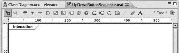
Figure 8.11: Sequence Diagram editor tool bar.
For the purpose of this illustration we’ll only be using a couple of these buttons, Create an actorand Add a message. Our objective here is to express the interactions among the classes in our system for the Press up/down button use case. Begin by creating an actor in the upper left-hand corner of the diagram and name it “passenger.”
Now the cool thing is that we can drag the classes from the elevator package in the Package Explorer view directly into the sequence diagram. Drag the classes so they show up in the following order to the right of the passenger:
1. UpDownButton
2. Controller
3. Elevator
4. Door
In order to get the Door class to show up you may have to maximize the editor window and drag the frame out to about 700 pixels. Then restore the editor to its windowed view. Your diagram should now look something like Figure 8.12. Each of the boxes is an instance of its respective class.
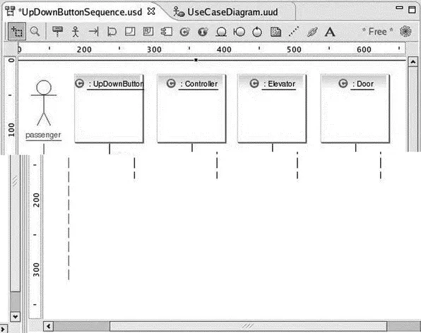
Figure 8.12: Sequence diagram with classes.
Note that the Outline view shows a thumbnail of the entire diagram with the portion visible in the Editor shaded. You can drag the shaded portion to scroll around in the Editor.
In the context of a sequence diagram, classes communicate by sending messages to each other. Click the Add a messagebutton, move the cursor to just below the label of the actor (his head turns blue) and click. Now move the cursor to the right until the UpDownButton box turns blue, and click. The Message dialog of Figure 8.13 comes up. Label it “Press.”
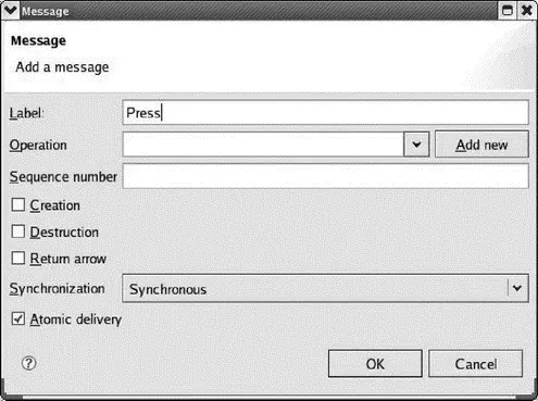
Figure 8.13: Message dialog.
Here you can also specify the Operation (method) that carries out the message. In this case, of course, there is none — the passenger is pressing the button. The commercial version of EclipseUML will add method templates to the class code. Leave the rest of the fields at their default values and click OK.
In like fashion, add a message labeled “update” from the UpDownButton to the Controller. You might want to grab the vertical box below the controller and drag it down a little to make it clear that the update follows the press. Next add a message from the Controller back to the UpDownButton and label it “illuminate.”
This gets a little tricky. The destination of a message can’t be the vertical bar (known as an “activation”) below a class instance. Note that when you drag the message wire over the activation bar, the international “no” symbol pops up. Drag the wire until the UpDownButton box is shaded blue, and click. Again, you’ll probably want to drag down the activation bar at the end of the illuminate message for readability. Your diagram should now look something like Figure 8.14.
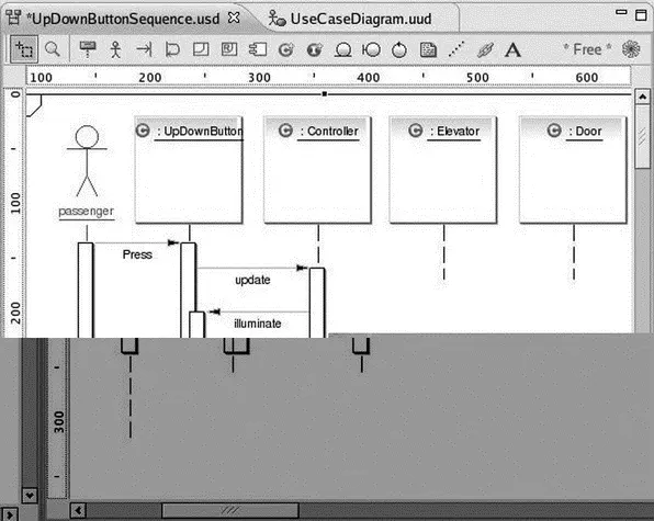
Figure 8.14: Sequence diagram with messages.
Continue adding messages to carry out the sequence of events listed above. After illuminating the button, the Controller will start the Elevator moving toward the specified floor. The Elevator will notify the Controller when it has reached the floor, whereupon the Controller will stop the Elevator and turn off the button illumination. Finally the Controller opens the Door and, after a suitable delay, closes the Door. The final diagram is shown in Figure 8.15.
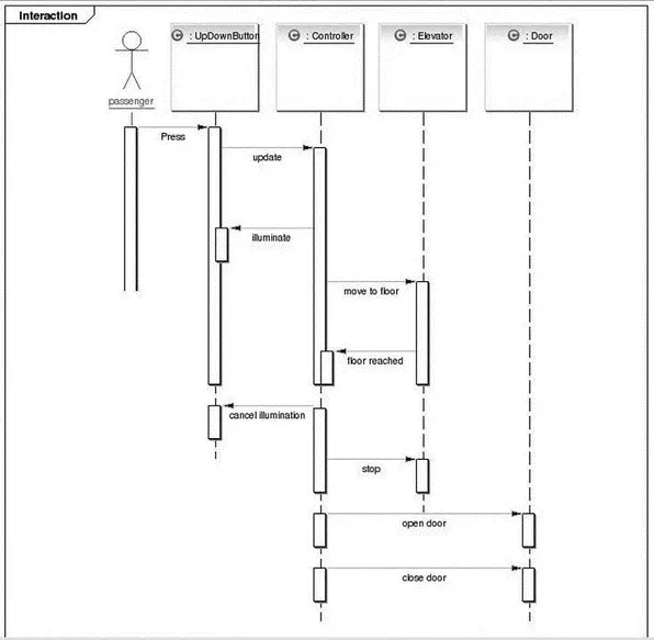
Figure 8.15: Completed sequence diagram.
Unfortunately, EclipseUML seems to have a mind of its own when it comes to vertical spacing of messages. It seems that some activation bars can be moved and resized, while other can’t. The resulting diagram is so big it requires a full screen to display.
We could continue looking at the other UML diagrams, but I think you get the idea. Feel free to play around with them and see what they do.
8.1.6 Configuring EclipseUML
EclipseUML has a number of configuration options. Click Window→Preferencesand select the UML entry. The top-level preferences dialog has four tabs. The Appearance tab is show in Figure 8.16. You may very well want to turn off the Show splash screen option. The tool bar can be displayed as text and/or images. The icon images can be either flat or embossed, although I can’t really see any difference.
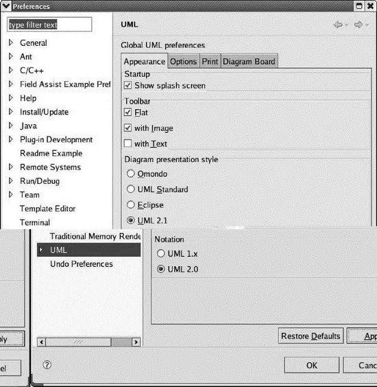
Figure 8.16: EclipseUML preferences.
Diagram presentation style offers some subtle variations in display, mainly involving shading. The differences are more apparent in the use case diagram than in the sequence diagram.
The Options and Print tabs are fairly self-explanatory. The Diagram Board tab offers options related to the grid and ruler, although it’s not obvious that they do anything.
Expand the UML preferences entry then expand Class Diagram. In the Association dialog is a Router option that specifies how lines, or “wires,” are drawn. The default is “Manhattan,” which routes the lines with right angles. The alternative is “Manual,” which runs the lines directly. Most of the other options are concerned with features of Java.
8.2 CVS
Back in the early days of embedded computing, a lone engineer would design the hardware and write the software, sometimes in assembly language. I did my share of that back in the day. In that kind of environment, keeping track of changes was no big deal. The entire program may have consisted of perhaps a dozen or so files, and it’s easy enough to wrap your mind around a project of that magnitude.
Needless to say, things have changed. Projects are not uncommon that contain hundreds, if not thousands of files being worked on by teams of developers who may be distributed all over the world. Now, keeping track of changes is a big deal. In fact, disciplined management of revisions is absolutely critical in maintaining control of the software development process. I even regret not having used version control on projects where I was the only developer.
CVS (Concurrent Versioning System) is an Open Source software package that supports simultaneous development of files by multiple developers. It is commonly used in large programming projects, but its use is not limited to software development. It can be useful in any task that involves managing files of data on a computer system.
Читать дальшеИнтервал:
Закладка:
Похожие книги на «Embedded Linux development using Eclipse»
Представляем Вашему вниманию похожие книги на «Embedded Linux development using Eclipse» списком для выбора. Мы отобрали схожую по названию и смыслу литературу в надежде предоставить читателям больше вариантов отыскать новые, интересные, ещё непрочитанные произведения.


Обсуждение, отзывы о книге «Embedded Linux development using Eclipse» и просто собственные мнения читателей. Оставьте ваши комментарии, напишите, что Вы думаете о произведении, его смысле или главных героях. Укажите что конкретно понравилось, а что нет, и почему Вы так считаете.