Christopher Hallinan - Embedded Linux Primer - A Practical, Real-World Approach
Здесь есть возможность читать онлайн «Christopher Hallinan - Embedded Linux Primer - A Practical, Real-World Approach» весь текст электронной книги совершенно бесплатно (целиком полную версию без сокращений). В некоторых случаях можно слушать аудио, скачать через торрент в формате fb2 и присутствует краткое содержание. Год выпуска: 2006, ISBN: 2006, Издательство: Prentice Hall, Жанр: ОС и Сети, на английском языке. Описание произведения, (предисловие) а так же отзывы посетителей доступны на портале библиотеки ЛибКат.

- Название:Embedded Linux Primer: A Practical, Real-World Approach
- Автор:
- Издательство:Prentice Hall
- Жанр:
- Год:2006
- ISBN:978-0-13-167984-9
- Рейтинг книги:4 / 5. Голосов: 1
-
Избранное:Добавить в избранное
- Отзывы:
-
Ваша оценка:
Embedded Linux Primer: A Practical, Real-World Approach: краткое содержание, описание и аннотация
Предлагаем к чтению аннотацию, описание, краткое содержание или предисловие (зависит от того, что написал сам автор книги «Embedded Linux Primer: A Practical, Real-World Approach»). Если вы не нашли необходимую информацию о книге — напишите в комментариях, мы постараемся отыскать её.
This book brings together indispensable knowledge for building efficient, high-value, Linux-based embedded products: information that has never been assembled in one place before. Drawing on years of experience as an embedded Linux consultant and field application engineer, Christopher Hallinan offers solutions for the specific technical issues you're most likely to face, demonstrates how to build an effective embedded Linux environment, and shows how to use it as productively as possible.
Hallinan begins by touring a typical Linux-based embedded system, introducing key concepts and components, and calling attention to differences between Linux and traditional embedded environments. Writing from the embedded developer's viewpoint, he thoroughly addresses issues ranging from kernel building and initialization to bootloaders, device drivers to file systems.
Hallinan thoroughly covers the increasingly popular BusyBox utilities; presents a step-by-step walkthrough of porting Linux to custom boards; and introduces real-time configuration via CONFIG_RT--one of today's most exciting developments in embedded Linux. You'll find especially detailed coverage of using development tools to analyze and debug embedded systems--including the art of kernel debugging.
• Compare leading embedded Linux processors
• Understand the details of the Linux kernel initialization process
• Learn about the special role of bootloaders in embedded Linux systems, with specific emphasis on U-Boot
• Use embedded Linux file systems, including JFFS2--with detailed guidelines for building Flash-resident file system images
• Understand the Memory Technology Devices subsystem for flash (and other) memory devices
• Master gdb, KGDB, and hardware JTAG debugging
• Learn many tips and techniques for debugging within the Linux kernel
• Maximize your productivity in cross-development environments
• Prepare your entire development environment, including TFTP, DHCP, and NFS target servers
• Configure, build, and initialize BusyBox to support your unique requirements
Embedded Linux Primer: A Practical, Real-World Approach — читать онлайн бесплатно полную книгу (весь текст) целиком
Ниже представлен текст книги, разбитый по страницам. Система сохранения места последней прочитанной страницы, позволяет с удобством читать онлайн бесплатно книгу «Embedded Linux Primer: A Practical, Real-World Approach», без необходимости каждый раз заново искать на чём Вы остановились. Поставьте закладку, и сможете в любой момент перейти на страницу, на которой закончили чтение.
Интервал:
Закладка:
* := unique name used in mapping driver/device (mtd->name)
* := std linux memsize OR "-" to denote all remaining space
* := '(' NAME ')'
Each mtddef parameter passed on the kernel command line defines a separate partition. As shown is Listing 10-10, each mtddef definition contains multiple parts. You can specify a unique ID, partition size, and offset from the start of the Flash. You can also pass the partition a name and, optionally, the read-only attribute. Referring back to our Redboot partition definitions in Listing 10-5, we could statically define these on the kernel command line as follows:
mtdparts=MainFlash:384K(Redboot),4K(config),128K(FIS),-(unused)
With this definition, the kernel would instantiate four MTD partitions, with an MTD ID of MainFlash, containing the sizes and layout matching that found in Listing 10-5.
10.3.3. Mapping Driver
The final method for defining your board-specific Flash layout is to use a dedicated board-specific mapping driver. The Linux kernel source tree contains many examples of mapping drivers, located in .../drivers/mtd/maps. Any one of these will provide good examples for how to create your own. The implementation details vary by architecture.
The mapping driver is a proper kernel module, complete with module_init() and module_exit() calls, as described in Chapter 8, "Device Driver Basics." A typical mapping driver is small and easy to navigate, often containing fewer than a couple dozen lines of C.
Listing 10-11 reproduces a section of .../drivers/mtd/maps/pq2fads. This mapping driver defines the Flash device on a Freescale PQ2FADS evaluation board that supports the MPC8272 and other processors.
Listing 10-11. PQ2FADs Flash Mapping Driver
...
static struct mtd_partition pq2fads_partitions[] = {
{
#ifdef CONFIG_ADS8272
.name = "HRCW",
.size = 0x40000,
.offset = 0,
.mask_flags= MTD_WRITEABLE, /* force read-only */
}, {
.name = "User FS",
.size = 0x5c0000,
.offset = 0x40000,
#else
.name = "User FS",
.size = 0x600000,
.offset = 0,
#endif
}, {
.name = "uImage",
.size = 0x100000,
.offset = 0x600000,
.mask_flags = MTD_WRITEABLE, /* force read-only */
}, {
.name = "bootloader",
.size = 0x40000,
.offset = 0x700000,
.mask_flags = MTD_WRITEABLE, /* force read-only */
}, {
.name = "bootloader env",
.size = 0x40000,
.offset = 0x740000,
.mask_flags = MTD_WRITEABLE, /* force read-only */
}
};
/* pointer to MPC885ADS board info data */
extern unsigned char __res[];
static int __init init_pq2fads_mtd(void) {
bd_t *bd = (bd_t *)__res;
physmap_configure(bd->bi_flashstart, bd->bi_flashsize, PQ2FADS_BANK_WIDTH, NULL);
physmap_set_partitions(pq2fads_partitions, sizeof (pq2fads_partitions) / sizeof (pq2fads_partitions[0]));
return 0;
}
static void __exit cleanup_pq2fads_mtd(void) {}
module_init(init_pq2fads_mtd);
module_exit(cleanup_pq2fads_mtd);
...
This simple but complete Linux device driver communicates the PQ2FADS Flash mapping to the MTD subsystem. Recall from Chapter 8 that when a function in a device driver is declared with the module_init() macro, it is automatically invoked during Linux kernel boot at the appropriate time. In this PQ2FADS mapping driver, the module initialization function init_pq2fads_mtd() performs just two simple calls:
• physmap_configure() passes to the MTD subsystem the Flash chip's physical address, size, and bank width, along with any special setup function required to access the Flash.
• physmap_set_partitions() passes the board's unique partition information to the MTD subsystem from the partition table defined in the pq2fads_partitions[] array found at the start of this mapping driver.
Following this simple example, you can derive a mapping driver for your own board.
10.3.4. Flash Chip Drivers
MTD has support for a wide variety of Flash chips and devices. Chances are very good that your chosen chip has also been supported. The most common Flash chips support the Common Flash Interface (CFI) mentioned earlier. Older Flash chips might have JEDEC support, which is an older Flash compatibility standard. Figure 10-4 shows the kernel configuration from a recent Linux kernel snapshot. This version supports many Flash types.
Figure 10-4. Flash device support
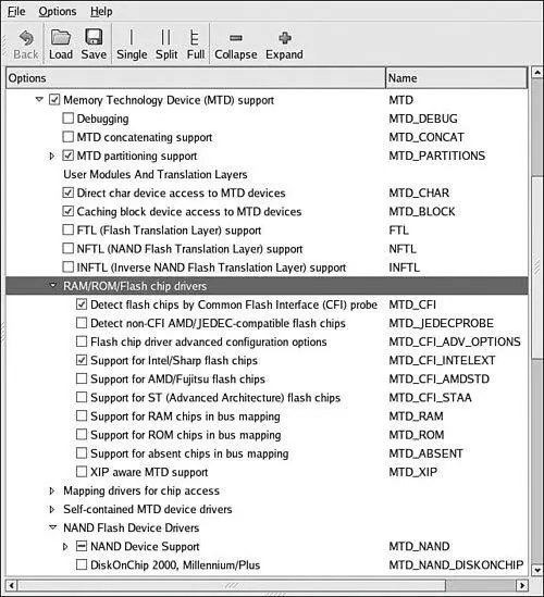
If your Flash chip is not supported, you must provide a device file yourself. Using one of the many examples in .../drivers/mtd/chips as a starting point, customize or create your own Flash device driver. Better yet, unless the chip was just introduced with some newfangled interface, chances are good that someone has already produced a driver.
10.3.5. Board-Specific Initialization
Along with a mapping driver, your board-specific (platform) setup must provide the underlying definitions for proper MTD Flash system operation. Listing 10-12 reproduces the relevant portions of .../arch/arm/mach-ixp4xx/coyote-setup.c.
Listing 10-12. Coyote-Specific Board Setup
static struct flash_platform_data coyote_flash_data = {
.map_name = "cfi_probe",
.width = 2,
};
static struct resource coyote_flash_resource = {
.start = COYOTE_FLASH_BASE,
.end = COYOTE_FLASH_BASE + COYOTE_FLASH_SIZE - 1,
.flags = IORESOURCE_MEM,
};
static struct platform_device coyote_flash = {
.name = "IXP4XX-Flash",
.id = 0,
.dev = {
.platform_data = &coyote_flash_data,
},
.num_resources = 1,
.resource = &coyote_flash_resource,
};
...
static struct platform_device *coyote_devices[] __initdata = {
&coyote_flash,
&coyote_uart
};
static void __init coyote_init(void) {
...
platform_add_devices(coyote_devices, ARRAY_SIZE(coyote_devices));
}
...
In Listing 10-12, only the relevant portions of the coyote-setup.c platform initialization file are reproduced. Starting from the bottom, the coyote_init() function calls platform_add_devices(), specifying the Coyote-specific devices defined earlier in this file. You'll notice that two devices are defined just above the coyote_init() routine. The one we're interested in for this discussion is coyote_flash. This structure of type struct platform_device contains all the important details needed by the Linux kernel and MTD subsystem.
The .name member of the coyote_flash structure binds our platform-specific Flash resource to a mapping driver with the same name. You can see this in the mapping driver file .../drivers/mtd/maps/ixp4xx.c. The .resource member communicates the base address of the Flash on the board. The .dev member, which contains a .platform_data member, ties our Flash setup to a chip driver. In this case, we have specified that our board will use the CFI probe method, specified in the kernel configuration as CONFIG_MTD_CFI. You can see this configuration selection in Figure 10-4.
Читать дальшеИнтервал:
Закладка:
Похожие книги на «Embedded Linux Primer: A Practical, Real-World Approach»
Представляем Вашему вниманию похожие книги на «Embedded Linux Primer: A Practical, Real-World Approach» списком для выбора. Мы отобрали схожую по названию и смыслу литературу в надежде предоставить читателям больше вариантов отыскать новые, интересные, ещё непрочитанные произведения.


Обсуждение, отзывы о книге «Embedded Linux Primer: A Practical, Real-World Approach» и просто собственные мнения читателей. Оставьте ваши комментарии, напишите, что Вы думаете о произведении, его смысле или главных героях. Укажите что конкретно понравилось, а что нет, и почему Вы так считаете.