Christopher Hallinan - Embedded Linux Primer - A Practical, Real-World Approach
Здесь есть возможность читать онлайн «Christopher Hallinan - Embedded Linux Primer - A Practical, Real-World Approach» весь текст электронной книги совершенно бесплатно (целиком полную версию без сокращений). В некоторых случаях можно слушать аудио, скачать через торрент в формате fb2 и присутствует краткое содержание. Год выпуска: 2006, ISBN: 2006, Издательство: Prentice Hall, Жанр: ОС и Сети, на английском языке. Описание произведения, (предисловие) а так же отзывы посетителей доступны на портале библиотеки ЛибКат.

- Название:Embedded Linux Primer: A Practical, Real-World Approach
- Автор:
- Издательство:Prentice Hall
- Жанр:
- Год:2006
- ISBN:978-0-13-167984-9
- Рейтинг книги:4 / 5. Голосов: 1
-
Избранное:Добавить в избранное
- Отзывы:
-
Ваша оценка:
Embedded Linux Primer: A Practical, Real-World Approach: краткое содержание, описание и аннотация
Предлагаем к чтению аннотацию, описание, краткое содержание или предисловие (зависит от того, что написал сам автор книги «Embedded Linux Primer: A Practical, Real-World Approach»). Если вы не нашли необходимую информацию о книге — напишите в комментариях, мы постараемся отыскать её.
This book brings together indispensable knowledge for building efficient, high-value, Linux-based embedded products: information that has never been assembled in one place before. Drawing on years of experience as an embedded Linux consultant and field application engineer, Christopher Hallinan offers solutions for the specific technical issues you're most likely to face, demonstrates how to build an effective embedded Linux environment, and shows how to use it as productively as possible.
Hallinan begins by touring a typical Linux-based embedded system, introducing key concepts and components, and calling attention to differences between Linux and traditional embedded environments. Writing from the embedded developer's viewpoint, he thoroughly addresses issues ranging from kernel building and initialization to bootloaders, device drivers to file systems.
Hallinan thoroughly covers the increasingly popular BusyBox utilities; presents a step-by-step walkthrough of porting Linux to custom boards; and introduces real-time configuration via CONFIG_RT--one of today's most exciting developments in embedded Linux. You'll find especially detailed coverage of using development tools to analyze and debug embedded systems--including the art of kernel debugging.
• Compare leading embedded Linux processors
• Understand the details of the Linux kernel initialization process
• Learn about the special role of bootloaders in embedded Linux systems, with specific emphasis on U-Boot
• Use embedded Linux file systems, including JFFS2--with detailed guidelines for building Flash-resident file system images
• Understand the Memory Technology Devices subsystem for flash (and other) memory devices
• Master gdb, KGDB, and hardware JTAG debugging
• Learn many tips and techniques for debugging within the Linux kernel
• Maximize your productivity in cross-development environments
• Prepare your entire development environment, including TFTP, DHCP, and NFS target servers
• Configure, build, and initialize BusyBox to support your unique requirements
Embedded Linux Primer: A Practical, Real-World Approach — читать онлайн бесплатно полную книгу (весь текст) целиком
Ниже представлен текст книги, разбитый по страницам. Система сохранения места последней прочитанной страницы, позволяет с удобством читать онлайн бесплатно книгу «Embedded Linux Primer: A Practical, Real-World Approach», без необходимости каждый раз заново искать на чём Вы остановились. Поставьте закладку, и сможете в любой момент перейти на страницу, на которой закончили чтение.
Интервал:
Закладка:
4690+1 records in
4690+1 records out
# mkdir /mnt/flash
# mount -t jffs2 /dev/mtdblock0/mnt/flash
# ls -l /mnt/flash
total 0
drwxr-xr-x 2 root root 0 Sep 17 22:02 bin
drwxr-xr-x 2 root root 0 Sep 17 21:59 dev
drwxr-xr-x 7 root root 0 Sep 17 15:31 etc
drwxr-xr-x 2 root root 0 Sep 17 15:31 home
drwxr-xr-x 2 root root 0 Sep 17 22:02 lib
drwxr-xr-x 2 root root 0 Sep 17 15:31 proc
drws------ 2 root root 0 Sep 17 15:31 root
drwxr-xr-x 2 root root 0 Sep 17 22:02 sbin
drwxrwxrwt 2 root root 0 Sep 17 15:31 tmp
drwxr-xr-x 9 root root 0 Sep 17 15:31 usr
drwxr-xr-x 14 root root 0 Sep 17 15:31 var
#
From Listing 10-3, first we install the loadable modules that the Linux kernel requires to support JFFS2 and the MTD subsystem. We load the JFFS2 module followed by the mTDblock and mtdram modules. After the necessary device drivers are loaded, we use the Linux dd command to copy our JFFS2 file system image into the MTD RAM test driver using the mTDblock device. In essence, we are using system RAM as a backing device to emulate an MTD block device.
After we have copied our JFFS2 file system image into the MTD block device, we can mount it using the mount command, in the manner shown in Listing 10-3. After the MTD pseudo-device has been mounted, we can work with the JFFS2 file system image in any way we choose. The only limitation using this method is that we can't enlarge the image. The size of the image is limited by two factors. First, when we configured the MTD RAM test device, we gave it a maximum size of 8MB. [75] The size was fixed in the kernel configuration when we enabled the MTD RAM test device in the Linux kernel configuration.
Second, when we created the JFFS2 image, we fixed the size of the image using the mkfs.jffs2 utility. The image size was determined by the contents of the directory we specified when we created it. Refer back to Listing 9-9, in Chapter 9, to recall how our jffs2.bin image was built.
It is important to realize the limitations of using this method to examine the contents of a JFFS2 file system. Consider what we did: We copied the contents of a file (the JFFS2 file system binary image) into a kernel block device (/dev/mtdblock0). Then we mounted the kernel block device (/dev/mtdblock) as a JFFS2 file system. After we did this, we could use all the traditional file system utilities to examine and even modify the file system. Tools such as ls, df, dh, mv, rm, and cp can all be used to examine and modify the file system. However, unlike the loopback device, there is no connection between the file we copied and the mounted JFFS2 file system image. Therefore, if we unmount the file system after making changes, the changes will be lost. If you want to save the changes, you must copy them back into a file. One such method is the following:
# dd if=/dev/mtdblock0 of=./your-modified-fs-image.bin
This command creates a file called your-modified-fs-image.bin that is the same size as the mtdblock0 device which was specified during configuration. In our example, it would be 8MB. Lacking suitable JFFS2 editing facilities, this is a perfectly valid way to examine and modify a JFFS2 file system. More important, it illustrates the basics of the MTD subsystem on our development system without real Flash memory. Now let's look at some hardware that contains Flash physical devices.
10.2.1. Configuring MTD
To use MTD with the Flash memory on your board, you must have MTD configured correctly. The following list contains the requirements that must be satisfied to configure MTD for your board, Flash, and Flash layout.
• Specify the partitioning on your Flash device
• Specify the type of Flash and location
• Configure the proper Flash driver for your chosen chip
• Configure the kernel with the appropriate driver(s)
Each of these steps is explored in the following sections.
10.3. MTD Partitions
Most Flash devices on a given hardware platform are divided into several sections, called partitions, similar to the partitions found on a typical desktop workstation hard drive. The MTD subsystem provides support for such Flash partitions. The MTD subsystem must be configured for MTD partitioning support. Figure 10-2 illustrates the configuration options for MTD partitioning support.
Figure 10-2. Kernel configuration for MTD partitioning support
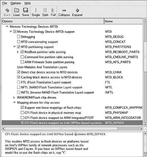
Several methods exist for communicating the partition data to the Linux kernel. The following methods are currently supported. You can see the configuration options for each in Figure 10-2 under MTD Partitioning Support.
• Redboot partition table parsing
• Kernel command-line partition table definition
• Board-specific mapping drivers
MTD also allows configurations without partition data. In this case, MTD simply treats the entire Flash memory as a single device.
10.3.1. Redboot Partition Table Partitioning
One of the more common methods of defining and detecting MTD partitions stems from one of the original implementations: Redboot partitions. Redboot is a bootloader found on many embedded boards, especially ARM XScale boards such as the ADI Engineering Coyote Reference Platform.
The MTD subsystem defines a method for storing partition information on the Flash device itself, similar in concept to a partition table on a hard disk. In the case of the Redboot partitions, the developer reserves and specifies a Flash erase block that holds the partition definitions. A mapping driver is selected that calls the partition parsing functions during boot to detect the partitions on the Flash device. Figure 10-2 shows the mapping driver for our example board; it is the final highlighted entry defining CONFIG_MTD_IXP4xx.
As usual, taking a detailed look at an example helps to illustrate these concepts. We start by looking at the information provided by the Redboot bootloader for the Coyote platform. Listing 10-4 captures some of the output of the Redboot bootloader upon power-up.
Listing 10-4. Redboot Messages on Power-Up
Platform: ADI Coyote (XScale)
IDE/Parallel Port CPLD Version: 1.0
Copyright (C) 2000, 2001, 2002, Red Hat, Inc.
RAM: 0x00000000-0x04000000, 0x0001f960-0x03fd1000 available
FLASH: 0x50000000 - 0x51000000, 128 blocks of 0x00020000 bytes each.
...
This tells us that RAM on this board is physically mapped starting at address 0x00000000 and that Flash is mapped at physical address 0x50000000 through 0x51000000. We can also see that the Flash has 128 blocks of 0x00020000 (128KB) each.
Redboot contains a command to create and display partition information on the Flash. Listing 10-5 contains the output of the fis list command, part of the Flash Image System family of commands available in the Redboot bootloader.
Listing 10-5. Redboot Flash Partition List
RedBoot> fis list
Name FLASH addr Mem addr Length Entry point
RedBoot 0x50000000 0x50000000 0x00060000 0x00000000
RedBoot config 0x50FC0000 0x50FC0000 0x00001000 0x00000000
Интервал:
Закладка:
Похожие книги на «Embedded Linux Primer: A Practical, Real-World Approach»
Представляем Вашему вниманию похожие книги на «Embedded Linux Primer: A Practical, Real-World Approach» списком для выбора. Мы отобрали схожую по названию и смыслу литературу в надежде предоставить читателям больше вариантов отыскать новые, интересные, ещё непрочитанные произведения.


Обсуждение, отзывы о книге «Embedded Linux Primer: A Practical, Real-World Approach» и просто собственные мнения читателей. Оставьте ваши комментарии, напишите, что Вы думаете о произведении, его смысле или главных героях. Укажите что конкретно понравилось, а что нет, и почему Вы так считаете.