Qing Li - Real-Time Concepts for Embedded Systems
Здесь есть возможность читать онлайн «Qing Li - Real-Time Concepts for Embedded Systems» весь текст электронной книги совершенно бесплатно (целиком полную версию без сокращений). В некоторых случаях можно слушать аудио, скачать через торрент в формате fb2 и присутствует краткое содержание. Город: San Francisco, Год выпуска: 2003, ISBN: 2003, Издательство: CMP books, Жанр: ОС и Сети, на английском языке. Описание произведения, (предисловие) а так же отзывы посетителей доступны на портале библиотеки ЛибКат.
- Название:Real-Time Concepts for Embedded Systems
- Автор:
- Издательство:CMP books
- Жанр:
- Год:2003
- Город:San Francisco
- ISBN:1-57820-124-1
- Рейтинг книги:4 / 5. Голосов: 1
-
Избранное:Добавить в избранное
- Отзывы:
-
Ваша оценка:
Real-Time Concepts for Embedded Systems: краткое содержание, описание и аннотация
Предлагаем к чтению аннотацию, описание, краткое содержание или предисловие (зависит от того, что написал сам автор книги «Real-Time Concepts for Embedded Systems»). Если вы не нашли необходимую информацию о книге — напишите в комментариях, мы постараемся отыскать её.
Delve into the details of real-time programming so you can develop a working knowledge of the common design patterns and program structures of real-time operating systems (RTOS). The objects and services that are a part of most RTOS kernels are described and real-time system design is explored in detail. You learn how to decompose an application into units and how to combine these units with other objects and services to create standard building blocks. A rich set of ready-to-use, embedded design “building blocks” is also supplied to accelerate your development efforts and increase your productivity.
Experienced developers new to embedded systems and engineering or computer science students will both appreciate the careful balance between theory, illustrations, and practical discussions. Hard-won insights and experiences shed new light on application development, common design problems, and solutions in the embedded space. Technical managers active in software design reviews of real-time embedded systems will find this a valuable reference to the design and implementation phases.
Qing Li is a senior architect at Wind River Systems, Inc., and the lead architect of the company’s embedded IPv6 products. Qing holds four patents pending in the embedded kernel and networking protocol design areas. His 12+ years in engineering include expertise as a principal engineer designing and developing protocol stacks and embedded applications for the telecommunications and networks arena. Qing was one of a four-member Silicon Valley startup that designed and developed proprietary algorithms and applications for embedded biometric devices in the security industry.
Caroline Yao has more than 15 years of high tech experience ranging from development, project and product management, product marketing, business development, and strategic alliances. She is co-inventor of a pending patent and recently served as the director of partner solutions for Wind River Systems, Inc. About the Authors
Real-Time Concepts for Embedded Systems — читать онлайн бесплатно полную книгу (весь текст) целиком
Ниже представлен текст книги, разбитый по страницам. Система сохранения места последней прочитанной страницы, позволяет с удобством читать онлайн бесплатно книгу «Real-Time Concepts for Embedded Systems», без необходимости каждый раз заново искать на чём Вы остановились. Поставьте закладку, и сможете в любой момент перейти на страницу, на которой закончили чтение.
Интервал:
Закладка:
Figure 16.3 shows the resource allocation graph. The graph represents the following:
· a circle represents a resource,
· a square represents a task or thread of execution,
· an arrow going from a task to a resource indicates that the task wants the resource, and
· an arrow going from a resource to a task indicates that the task currently holds the resource.
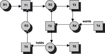
Figure 16.3: Current state of resource allocations and requests.
In the following discussions, node refers either to the circle (resource) or the square (task) in Figure 16.3. Arc refers to the arrow. The deadlock detection algorithm can be stated in these seven steps:
1. Make a list of all the nodes, N , from the graph.
2. Pick a node from N . Create another list, L , initially empty, which is used for the graph traversal.
3. Insert the node into L and check if this node already exists in L . If so, a cycle exists; therefore, a deadlock is detected, and the algorithm terminates. Otherwise, remove the node from N .
4. Check whether any un-traversed outgoing arcs from this node exist. If all of the arcs are traversed, go to step 6.
5. Choose an un-traversed outgoing arc originating from the node and mark the arc as traversed. Follow the chosen arc to the new node and return to step 3.
6. At this stage, a path in the graph terminates, and no deadlocks exist. If more than one entry is in L , remove the last entry from L . If more than one entry remains in L , make the last entry of L the current node and go to step 4.
7. If the list N is not empty, go to step 2. Otherwise, the algorithm terminates, and no deadlocks exist in the system.
The actual implementation from step 3 to step 6 translates into a depth first search of the directed graph.
Applying this algorithm to the system depicted in Figure 16.3 provides the following:
Step 1: N = {R1, T1, R2, T2, R3, T3, R4, T4, T5, R5, T6}
Step 2: L = {‹ empty ›}; pick node R1
Step 3: L = {R1}; no cycles are in L; N = {T1, R2, T2, R3, T3, R4, T4, T5, R5, T6}
Step 4:R1 has one outgoing arc
Step 5:Mark the arc; reaches node T1; go back to step 3
Step 3: L = {R1, T1}; N = {R2, T2, R3, T3, R4, T4, T5, R5, T6}; no cycles are in L
The algorithm continues from step 3 to step 5 and reiterates until it reaches node T3, in which the list L = {R1, T1, R2, T2, R4, T3} and the list N = {R3, T4, T5, R5, T6}. Two outgoing arcs are at node T3. When the downward arc is picked, L = {R1, T1, R2, T2, R4, T3, R5}. Two outgoing arcs are at node R5. When the rightward arc is picked, L = {R1, T1, R2, T2, R4, T3, R5, T6}.
Step 4:T6 does not have any outgoing arcs; continue to step 6
Step 6:Remove T6 from the list L; L = {R1, T1, R2, T2, R4, T3, R5}; return to step 4
Step 4:Pick the unmarked leftward arc at R5
Step 5:Mark the arc; reaches node T5; return to step 3
Step 3: L = {R1, T1, R2, T2, R4, T3, R5, T5}; N = {R3, T4}; no cycles are in L
Step 4:Pick the only outgoing arc at T5
Step 5:Mark the arc; reaches node R3; go back to step 3
Step 3: L = {R1, T1, R2, T2, R4, T3, R5, T5, R3}; N = {T4}; still no cycles are in L
Step 4:Pick the only outgoing arc at R3
Step 5:Mark the arc; reaches node T1; go back to step 3
Step 3: L = {R1, T1, R2, T2, R4, T3, R5, T5, R3, T1}; Node T1 already exists in L . A cycle is found in the graph, and a deadlock exists. The algorithm terminates.
The deadlock set is comprised of the entire nodes enclosed by the two occurrences of node T1 inclusively. Therefore, the discovered deadlock set is {T1, R2, T2, R4, T3, R5, T5, R3}. One thing worth noting is that the algorithm detects deadlocks if any exist. Which deadlock is detected first depends on the structure of the graph. Closer examination of the resource graph reveals that another deadlock exists. That deadlock set is {R2, T2, R4, T3}. At node T3 if the upward arc is chosen first instead of the downward arc, this later deadlock occurrence would be discovered, and the algorithm would terminate much sooner.
The deadlock detection algorithm takes a different approach for systems with multiple instances of each resource type, and tasks make resource requests following the AND model. An underlying assumption is that a resource allocation system is present. The resource allocation system is comprised of a set of different types of resources, R1, R2, R3,…, R n . Each type of resource has a fixed number of units. The resource allocation system maintains a resource allocation table and a resource demand table.
Each row of tables C and D represents a task T. Each column of tables C and D is associated with a resource type. C is the resource allocation table representing resources already allocated. D is the resource demand table representing additional resources required by the tasks.
| N = Total System Resources Table | N 1 | N 2 | N 3 | … | N k |
where N i is the number of units of resource type R i for all i where {1 ≤ i ≤ k }.
| A = Available System Resources Table | A 1 | A 2 | A 3 | … | A k |
where A i the number of units remaining for resource type R i available for allocation.
| C = Tasks Resources Assigned Table | C 11 | C 12 | C 13 | … | C 1 k |
| C 21 | C 22 | … | C 2 k | ||
| … | … | ||||
| C m 1 | … | C mk | |||
| D = Tasks Resources Demand Table | D 11 | D 12 | D 13 | … | D 1 k |
| D 21 | D 22 | … | D 2 k | ||
| … | … | ||||
| D m 1 | … | D mk |
For example in table C, there are C 11units of resource R1, C 12units of resource R2, and so on, which are allocated to task T1. Similarly, there are C 21units of resource R1, C 22units of resource R2, and so on, which are allocated to task T2. For example in table D, task T1 demands additional D 11units of resource R1, additional D 12units of resource R2, and so on, in order to complete execution.
The deadlock detection algorithm is as follows:
1. Find a row i in table D, where D ij ‹ A j for all 1 ≤ j ≤ k . If no such row exists, the system is deadlocked, and the algorithm terminates.
2. Mark the row i as complete and assign A j = A j + D ij for all 1 ≤ j ≤ k .
3. If an incomplete row is present, return to step 1. Otherwise, no deadlock is in the system, and the algorithm terminates.
Step 1 of the algorithm looks for a task whose resource requirements can be satisfied. If such a task exists, the task can run to completion. Resources from the completed task are freed back into the resource pool, which step 2 does. The newly available resources can be used to meet the requirements of other tasks, which allow them to resume execution and run to completion.
Читать дальшеИнтервал:
Закладка:
Похожие книги на «Real-Time Concepts for Embedded Systems»
Представляем Вашему вниманию похожие книги на «Real-Time Concepts for Embedded Systems» списком для выбора. Мы отобрали схожую по названию и смыслу литературу в надежде предоставить читателям больше вариантов отыскать новые, интересные, ещё непрочитанные произведения.


Обсуждение, отзывы о книге «Real-Time Concepts for Embedded Systems» и просто собственные мнения читателей. Оставьте ваши комментарии, напишите, что Вы думаете о произведении, его смысле или главных героях. Укажите что конкретно понравилось, а что нет, и почему Вы так считаете.