Qing Li - Real-Time Concepts for Embedded Systems
Здесь есть возможность читать онлайн «Qing Li - Real-Time Concepts for Embedded Systems» весь текст электронной книги совершенно бесплатно (целиком полную версию без сокращений). В некоторых случаях можно слушать аудио, скачать через торрент в формате fb2 и присутствует краткое содержание. Город: San Francisco, Год выпуска: 2003, ISBN: 2003, Издательство: CMP books, Жанр: ОС и Сети, на английском языке. Описание произведения, (предисловие) а так же отзывы посетителей доступны на портале библиотеки ЛибКат.
- Название:Real-Time Concepts for Embedded Systems
- Автор:
- Издательство:CMP books
- Жанр:
- Год:2003
- Город:San Francisco
- ISBN:1-57820-124-1
- Рейтинг книги:4 / 5. Голосов: 1
-
Избранное:Добавить в избранное
- Отзывы:
-
Ваша оценка:
Real-Time Concepts for Embedded Systems: краткое содержание, описание и аннотация
Предлагаем к чтению аннотацию, описание, краткое содержание или предисловие (зависит от того, что написал сам автор книги «Real-Time Concepts for Embedded Systems»). Если вы не нашли необходимую информацию о книге — напишите в комментариях, мы постараемся отыскать её.
Delve into the details of real-time programming so you can develop a working knowledge of the common design patterns and program structures of real-time operating systems (RTOS). The objects and services that are a part of most RTOS kernels are described and real-time system design is explored in detail. You learn how to decompose an application into units and how to combine these units with other objects and services to create standard building blocks. A rich set of ready-to-use, embedded design “building blocks” is also supplied to accelerate your development efforts and increase your productivity.
Experienced developers new to embedded systems and engineering or computer science students will both appreciate the careful balance between theory, illustrations, and practical discussions. Hard-won insights and experiences shed new light on application development, common design problems, and solutions in the embedded space. Technical managers active in software design reviews of real-time embedded systems will find this a valuable reference to the design and implementation phases.
Qing Li is a senior architect at Wind River Systems, Inc., and the lead architect of the company’s embedded IPv6 products. Qing holds four patents pending in the embedded kernel and networking protocol design areas. His 12+ years in engineering include expertise as a principal engineer designing and developing protocol stacks and embedded applications for the telecommunications and networks arena. Qing was one of a four-member Silicon Valley startup that designed and developed proprietary algorithms and applications for embedded biometric devices in the security industry.
Caroline Yao has more than 15 years of high tech experience ranging from development, project and product management, product marketing, business development, and strategic alliances. She is co-inventor of a pending patent and recently served as the director of partner solutions for Wind River Systems, Inc. About the Authors
Real-Time Concepts for Embedded Systems — читать онлайн бесплатно полную книгу (весь текст) целиком
Ниже представлен текст книги, разбитый по страницам. Система сохранения места последней прочитанной страницы, позволяет с удобством читать онлайн бесплатно книгу «Real-Time Concepts for Embedded Systems», без необходимости каждый раз заново искать на чём Вы остановились. Поставьте закладку, и сможете в любой момент перейти на страницу, на которой закончили чтение.
Интервал:
Закладка:
At the completion of the application decomposition process, robust systems must validate the schedulability of the newly formed tasks. Quantitative schedulability analysis on a real-time system determines whether the system as designed is schedulable. A real-time system is considered schedulable if every task in the system can meet its deadline.
This chapter also focuses on the schedulability analysis (Step 8). In particular, the chapter introduces a formal method known as Rate Monotonic Analysis (RMA).
14.2 An Outside-In Approach to Decomposing Applications
In most cases, designers insist on a set of requirements before beginning work on a real-time embedded system. If the requirements are not fully defined, one of the first activities is to ensure that many of these requirements are solidified. Ambiguous areas also need to be fleshed out. The detailed requirements should be captured in a document, such as a Software Requirements Specification (SRS). Only then can an engineering team make a reasonable attempt at designing a system. A high-level example of a mobile phone design is provided to show how to decompose an application into concurrent units of execution.
Commonly, decomposing an application is performed using an outside-in approach. This approach follows a process of identifying the inputs and outputs of a system and expressing them in a simple high-level context diagram. A context diagram for the mobile application is illustrated in Figure 14.1. The circle in the center of the diagram represents the software application. Rectangular boxes represent the input and output devices for this application. In addition, arrows, labeled with meaningful names, represent the flow of the input and output communications. For the sake of simplicity, not all components (i.e., battery, input for hands-free ear plug, input for external power, and power on/off button) are illustrated.
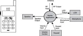
Figure 14.1: High-level context diagram of a mobile handheld unit.
The diagram shows that mobile handset application provides interfaces for the following I/O devices:
· antenna,
· speaker,
· volume control,
· keypad,
· microphone, and
· LCD.
The following inputs are identified:
· RF input,
· volume input,
· keypad input, and
· microphone input.
The following outputs are identified:
· RF output,
· speaker output, and
· LCD output.
After the inputs and outputs are identified, a first cut at decomposing the application can be made. Figure 14.2 shows an expanded diagram of the circle identifying some of the potential tasks into which the application can decompose. These tasks are along the edges of the newly drawn application, which means they probably must interact with the outside world. Note that these tasks are not the only ones required, but the process provides a good starting point. Upon further analysis, additional tasks may be identified, or existing tasks may be combined as more details are considered.
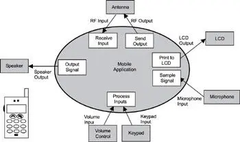
Figure 14.2: Using the outside-in approach to decompose an application into tasks.
Some inputs and outputs in a handheld mobile device can require more than one dedicated task to handle processing. Conversely, in some cases, a single task can handle multiple devices. Looking at the example, the antenna can have two tasks assigned to it-one for handling the incoming voice channel and one for handling the outgoing voice channel. Printing to the LCD can be a relatively simple activity and can be handled with one task. Similarly, sampling the input voice from the microphone can also be handled with one task for now but might require another task if heavy computation is required for sampling accuracy. Note that one task can handle the input keys and the volume control. Finally, a task is designated for sending the output to the speaker.
This example illustrates why the decomposition method is called outside-in: an engineering team can continue this way to decompose the overall application into tasks from the outside in.
14.3 Guidelines and Recommendations for Identifying Concurrency
The outside-in approach to decomposing an application is an example of one practical way to identify types of concurrent tasks that are dependent on or interact with I/O devices. The mobile handset example expands a high-level context diagram to determine some of the obvious tasks required to handle certain events or actions. Further refinement of this diagram would yield additional tasks. More formalized ways of identifying concurrency exist, however. Many guidelines are provided in this section to help the reader identify concurrency in an application. First, let's introduce a couple of concepts that are important to understanding concurrency.
14.3.1 Units of Concurrency
It is important to encapsulate concurrency within an application into manageable units. A unit of concurrency can be a task or a process; it can be any schedulable thread of execution that can compete for the CPU's processing time. Although ISRs are not scheduled to run concurrently with other routines, they should also be considered in designing for concurrency because they follow a preemptive policy and are units of execution competing for CPU processing time. The primary objective of this decomposition process is to optimize parallel execution to maximize a real-time application's performance and responsiveness. If done correctly, the result can be a system that meets all of its deadlines robustly and responsively. If done incorrectly, real-time deadlines can be compromised, and the system's design may not be acceptable.
14.3.2 Pseudo versus True Concurrent Execution
Concurrent tasks in a real-time application can be scheduled to run on a single processor or multiple processors. Single-processor systems can achieve pseudo concurrent execution, in which an application is decomposed into multiple tasks maximizing the use of a single CPU. It is important to note that on a single-CPU system, only one program counter (also called an instruction pointer) is used, and, hence, only one instruction can be executed at any time. Most applications in this environment use an underlying scheduler's multitasking capabilities to interleave the execution of multiple tasks; therefore, the term pseudo concurrent execution is used.
In contrast, true concurrent execution can be achieved when multiple CPUs are used in the designs of real-time embedded systems. For example, if two CPUs are used in a system, two concurrent tasks can execute in parallel at one time, as shown in Figure 14.3. This parallelism is possible because two program counters (one for each CPU) are used, which allows for two different instructions to execute simultaneously.
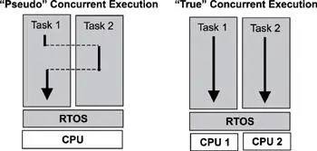
Figure 14.3: Pseudo and true concurrent (parallel) execution.
In the case of multiple CPU systems, the underlying RTOS typically is distributed, which means that various components, or copies of RTOS components, can execute on different CPUs. On such systems, multiple tasks can be assigned to run on each CPU, just as they do on single-CPU systems. In this case, even though two or more CPUs allow true concurrent execution, each CPU might actually be executing in a pseudo-concurrent fashion.
Читать дальшеИнтервал:
Закладка:
Похожие книги на «Real-Time Concepts for Embedded Systems»
Представляем Вашему вниманию похожие книги на «Real-Time Concepts for Embedded Systems» списком для выбора. Мы отобрали схожую по названию и смыслу литературу в надежде предоставить читателям больше вариантов отыскать новые, интересные, ещё непрочитанные произведения.


Обсуждение, отзывы о книге «Real-Time Concepts for Embedded Systems» и просто собственные мнения читателей. Оставьте ваши комментарии, напишите, что Вы думаете о произведении, его смысле или главных героях. Укажите что конкретно понравилось, а что нет, и почему Вы так считаете.