Qing Li - Real-Time Concepts for Embedded Systems
Здесь есть возможность читать онлайн «Qing Li - Real-Time Concepts for Embedded Systems» весь текст электронной книги совершенно бесплатно (целиком полную версию без сокращений). В некоторых случаях можно слушать аудио, скачать через торрент в формате fb2 и присутствует краткое содержание. Город: San Francisco, Год выпуска: 2003, ISBN: 2003, Издательство: CMP books, Жанр: ОС и Сети, на английском языке. Описание произведения, (предисловие) а так же отзывы посетителей доступны на портале библиотеки ЛибКат.
- Название:Real-Time Concepts for Embedded Systems
- Автор:
- Издательство:CMP books
- Жанр:
- Год:2003
- Город:San Francisco
- ISBN:1-57820-124-1
- Рейтинг книги:4 / 5. Голосов: 1
-
Избранное:Добавить в избранное
- Отзывы:
-
Ваша оценка:
Real-Time Concepts for Embedded Systems: краткое содержание, описание и аннотация
Предлагаем к чтению аннотацию, описание, краткое содержание или предисловие (зависит от того, что написал сам автор книги «Real-Time Concepts for Embedded Systems»). Если вы не нашли необходимую информацию о книге — напишите в комментариях, мы постараемся отыскать её.
Delve into the details of real-time programming so you can develop a working knowledge of the common design patterns and program structures of real-time operating systems (RTOS). The objects and services that are a part of most RTOS kernels are described and real-time system design is explored in detail. You learn how to decompose an application into units and how to combine these units with other objects and services to create standard building blocks. A rich set of ready-to-use, embedded design “building blocks” is also supplied to accelerate your development efforts and increase your productivity.
Experienced developers new to embedded systems and engineering or computer science students will both appreciate the careful balance between theory, illustrations, and practical discussions. Hard-won insights and experiences shed new light on application development, common design problems, and solutions in the embedded space. Technical managers active in software design reviews of real-time embedded systems will find this a valuable reference to the design and implementation phases.
Qing Li is a senior architect at Wind River Systems, Inc., and the lead architect of the company’s embedded IPv6 products. Qing holds four patents pending in the embedded kernel and networking protocol design areas. His 12+ years in engineering include expertise as a principal engineer designing and developing protocol stacks and embedded applications for the telecommunications and networks arena. Qing was one of a four-member Silicon Valley startup that designed and developed proprietary algorithms and applications for embedded biometric devices in the security industry.
Caroline Yao has more than 15 years of high tech experience ranging from development, project and product management, product marketing, business development, and strategic alliances. She is co-inventor of a pending patent and recently served as the director of partner solutions for Wind River Systems, Inc. About the Authors
Real-Time Concepts for Embedded Systems — читать онлайн бесплатно полную книгу (весь текст) целиком
Ниже представлен текст книги, разбитый по страницам. Система сохранения места последней прочитанной страницы, позволяет с удобством читать онлайн бесплатно книгу «Real-Time Concepts for Embedded Systems», без необходимости каждый раз заново искать на чём Вы остановились. Поставьте закладку, и сможете в любой момент перейти на страницу, на которой закончили чтение.
Интервал:
Закладка:
Tips on section allocation include the following:
· allocate sections according to size to fully use available memory, and
· examine the nature of the underlying physical memory, the attributes, and the purpose of a section to determine which physical memory is best suited for allocation.
2.4.2 Mapping Executable Images
Various reasons exist why an embedded developer might want to define custom sections, as well as to map these sections into different target memory areas as shown in the last example. The following sections list some of these reasons.
Chapter 1 discusses the storage options and upgradability of software on embedded systems. Software can be easily upgraded when stored in non-volatile memory devices, such as flash devices. It is possible to upgrade the software dynamically while the system is still running. Upgrading the software can involve downloading the new program image over either a serial line or a network and then re-programming the flash memory. The loader in the example could be such an application. The initial version of the loader might be capable of transferring an image from ROM to RAM. A newer version of the loader might be capable of transferring an image from the host over the serial connection to RAM. Therefore, the loader code and data section would be created in a custom loader section. The entire section then would be programmed into the flash memory for easy upgradeability in the future.
The target system usually has different types of physical memory, but each is limited in size. At times, it is impossible to fit all of the code and data into one type of memory, for example, the SDRAM. Because SDRAM has faster access time than DRAM, it is always desirable to map code and data into it. The available physical SDRAM might not be large enough to fit everything, but plenty of DRAM is available in the system. Therefore, the strategy is to divide the program into multiple sections and have some sections allocated into the SDARM, while the rest is mapped into the DRAM. For example, an often-used function along with a frequently searched lookup table might be mapped to the SDRAM. The remaining code and data is allocated into the DRAM.
Programs usually have various types of constants, such as integer constants and string constants. Sometimes these constants are kept in ROM to avoid accidental modification. In this case, these constants are part of a special data section, which is allocated into ROM.
2.4.3 Example in Practice
Consider an example system containing 256 bytes of ROM, 16KB of flash memory, and two blocks of RAM. RAMB0 is 128KB of SDRAM, and RAMB1 is 2MB of DRAM. An embedded application with a number of sections, as listed in Table 2.3, needs to be mapped into this target system.
Table 2.3: Example embedded application with sections.
| Sections | Size | Attribute [1] RD = read only; R/W = readable and writeable |
Description |
|---|---|---|---|
| _loader | 10KB | RD | Contains the loader code |
| _wflash | 2KB | RD | Contains the flash memory programmer |
| .rodata | 128 bytes | RD | Contains non-volatile default initialization parameters and data, such as copyright information |
| .sbss | 10KB | R/W | Contains uninitialized data less than 64KB (e.g., global variables) |
| .sdata | 2KB | R/W | Contains initialized data less than 64KB |
| .bss | 128KB | R/W | Contains uninitialized data larger than 64KB |
| .data | 512KB | R/W | Contains initialized data larger than 64KB |
| _monitor | 54KB | RD | Contains the monitor code |
| .text | 512KB | RD | Contains other program code |
One possible allocation is shown in Listing 2.5; it considers why an embedded engineer might want greater section allocation control.
Listing 2.5: Possible section allocation.
MEMORY {
ROM: origin = 0x00000h, length = 0x000100h
FLASH: origin = 0x00110h, length = 0x004000h
RAMB0: origin = 0x05000h, length = 0x020000h
RAMB1: origin = 0x25000h, length = 0x200000h
}
SECTION {
.rodata: › ROM
_loader: › FLASH
_wflash: › FLASH
_monitor: › RAMB0
.sbss (ALIGN 4): › RAMB0
.sdata (ALIGN 4): › RAMB0
.text: › RAMB1
.bss (ALIGN 4): › RAMB1
.data (ALIGN 4): › RAMB1
}
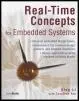
This program allocation is shown in Figure 2.8. The section allocation strategies applied include the following:
· The .rodata section contains system initialization parameters. Most likely these default values never change; therefore, allocate this section to ROM.
· The loader program is usually part of the system program that executes at startup. The _loader and the _wflash sections are allocated into flash memory because the loader code can be updated with new versions that understand more object formats. You need the flash memory programmer for this purpose, which can also be updated. Therefore, section _wflash is allocated into the flash memory as well.
· The embedded programmer interacts with the monitor program to probe system execution states and help debug application code; therefore, it should be responsive to user commands. SDRAM is faster than DRAM, with shorter access time. Therefore, section _monitor is allocated into RAMB0.
· RAMB0 still has space left to accommodate both sections.sbss and.sdata. The allocation strategy for these two sections is to use the leftover fast memory fully.
· The remaining sections (.text, .bss, and .data) are allocated into RAMB1, which is the only memory that can accommodate all of these large sections.
Figure 2.8: Mapping an executable image into the target system.
2.5 Points to Remember
Some points to remember include the following:
· The linker performs symbol resolution and symbol relocation.
· An embedded programmer must understand the exact memory layout of the target system towards which development is aimed.
· An executable target image is comprised of multiple program sections.
· The programmer can describe the physical memory, such as its size and its mapping address, to the linker using the linker command file. The programmer can also instruct the linker on combining input sections into output sections and placing the output program sections using the linker command file.
· Each program section can reside in different types of physical memory, based on how the section is used. Program code (or.text section) can stay in ROM, flash, and RAM during execution. Program data (or.data section) must stay in RAM during execution.
Chapter 3: Embedded System Initialization
3.1 Introduction
It takes just minutes for a developer to compile and run a “Hello World!” application on a non-embedded system. On the other hand, for an embedded developer, the task is not so trivial. It might take days before seeing a successful result. This process can be a frustrating experience for a developer new to embedded system development.
Читать дальшеИнтервал:
Закладка:
Похожие книги на «Real-Time Concepts for Embedded Systems»
Представляем Вашему вниманию похожие книги на «Real-Time Concepts for Embedded Systems» списком для выбора. Мы отобрали схожую по названию и смыслу литературу в надежде предоставить читателям больше вариантов отыскать новые, интересные, ещё непрочитанные произведения.


Обсуждение, отзывы о книге «Real-Time Concepts for Embedded Systems» и просто собственные мнения читателей. Оставьте ваши комментарии, напишите, что Вы думаете о произведении, его смысле или главных героях. Укажите что конкретно понравилось, а что нет, и почему Вы так считаете.