John Crisp - Introduction to Microprocessors and Microcontrollers
Здесь есть возможность читать онлайн «John Crisp - Introduction to Microprocessors and Microcontrollers» весь текст электронной книги совершенно бесплатно (целиком полную версию без сокращений). В некоторых случаях можно слушать аудио, скачать через торрент в формате fb2 и присутствует краткое содержание. Год выпуска: 2004, ISBN: 2004, Издательство: Elsevier, Жанр: Компьютерное железо, на английском языке. Описание произведения, (предисловие) а так же отзывы посетителей доступны на портале библиотеки ЛибКат.
- Название:Introduction to Microprocessors and Microcontrollers
- Автор:
- Издательство:Elsevier
- Жанр:
- Год:2004
- ISBN:0-7506-5989-0
- Рейтинг книги:3 / 5. Голосов: 1
-
Избранное:Добавить в избранное
- Отзывы:
-
Ваша оценка:
Introduction to Microprocessors and Microcontrollers: краткое содержание, описание и аннотация
Предлагаем к чтению аннотацию, описание, краткое содержание или предисловие (зависит от того, что написал сам автор книги «Introduction to Microprocessors and Microcontrollers»). Если вы не нашли необходимую информацию о книге — напишите в комментариях, мы постараемся отыскать её.
Introduction to Microprocessors and Microcontrollers — читать онлайн бесплатно полную книгу (весь текст) целиком
Ниже представлен текст книги, разбитый по страницам. Система сохранения места последней прочитанной страницы, позволяет с удобством читать онлайн бесплатно книгу «Introduction to Microprocessors and Microcontrollers», без необходимости каждый раз заново искать на чём Вы остановились. Поставьте закладку, и сможете в любой момент перейти на страницу, на которой закончили чтение.
Интервал:
Закладка:
Appendix A: Special function register file
| Addr | Name | Bit 7 | Bit 6 | Bit 5 | Bit 4 | Bit 3 | Bit 2 | Bit 1 | Bit 0 | Power-on Reset |
|---|---|---|---|---|---|---|---|---|---|---|
| BANK 0 | ||||||||||
| 00H | Uses contents of FSR to address data memory (not a physical register) | |||||||||
| 01H | TMRO | 8-bit real-time clock/counter | xxxxxxxx | |||||||
| 02H | PCL | Low order 8 bits of the program counter (PC) | 00000000 | |||||||
| 03H | Status | IRP | RP1 | RPO | TO | PD | Z | DC | C | 00011xxx |
| 04H | FSR | Indirect Data Mamory Address Pointer | xxxxxxxx | |||||||
| 05H | PortA | – | – | – | RA4/T-CKI | RA3 | RA2 | RA1 | RA0 | ---x xxxx |
| 06H | PortB | RB7 | RB6 | RB5 | RB4 | RB3 | RB2 | RB1 | RB0/INT | xxxxxxxx |
| 07H | – | Unused | ||||||||
| BANK 1 | ||||||||||
| 81H | Option | RBPU | INTEDG | T0CS | T0SE | PSA | PS2 | PS1 | PS0 | 11111111 |
| 85H | TRISA | – | – | – | PortA data Direction | ---11111 | ||||
| 86H | TRISB | PortB data Direction | 11111111 | |||||||
| 87H | – | Unused | ||||||||
| 88H | EECON 1 | – | – | – | EEIF | WRERR | WREN | WR | RD | ---0x000 |
| 89H | EECON 2 | EEPROM control reg. (not a physical register) | ------- |
The full details (85 pages) of absolutely everything about the PIC16F84A (or any other PIC) can be downloaded from www.microchip.com.
Appendix B: PIC 16CXXX instruction set
| Syntax | Description | Status affected |
|---|---|---|
| ADDLW k | The contents of the W register are added to an 8-bit number and the result put in the W reg. | C, DC, Z |
| ADDWF f,d | Add the contents of the W and f registers. If d=0 the result goes to W. If d=1 the result goes to the f register | C, DC, Z |
| ANDLW k | The contents of the W register are ANDed with an 8-bit number and the result put in the W reg. | Z |
| ANDWF f,d | AND w with reg f. If d=0 the result goes to W. If d=1 the result goes to the f register | Z |
| BCF f,b | Bit b in reg f is cleared | |
| BSF f,b | Bit b in reg f is set | |
| BTFSS f,b | If bit b in reg f=0, the next instruction in executed. If it is 1 the next instr. is replaced with a NOP | 1 or 2 cycles |
| BTFSC f,b | If bit b in reg f=1, the next instruction in executed. If it is 0 the next instr. is replaced with a NOP | 1 or 2 cycles |
| CALL k | Call subroutine. Return address (PC+1) is pushed onto stack. The 11-bit immediate address is loaded into PC bits 1:0 The upper bits of the PC are loaded from PCLATH 4:3. | 2 cycle |
| CLRF | f Register f is cleared and Z flag is set. | Z |
| CLRW | Register W is cleared and Z flag is set. | Z |
| CLRWDT | Resets watchdog timer and watchdog prescaler | TO, PD |
| COMF f,d | Contents of ‘f’ are complemented (0→1, 1→0) If d=0 the result goes to W. If d=1 the result goes to f | Z |
| DECF f,d | Contents of ‘f’ reduced by 1. If d=0 the result goes to W. If d = 1 the result goes to f | Z |
| DECFSZ f,d | Contents of ‘f’ reduced by 1. if d=0 the result goes to W. If d=1 the result goes to f. If result = 1, the next instruction in executed. If it is 0 the next instr. is replaced with a NOP | 1 or 2 cycles |
| GOTO k | The 11-bit immediate address is loaded into PC bits <10:0>. The upper bits of the PC are loaded from PCLATH <4:3>. | |
| INCF f,d | If d=0 the result goes to W. If d=1, result goes to f. | |
| INCFSZ f,d | Contents of ‘f’ incremented. If d=0 the result goes to W. If d=1 the result goes to f. If rfesult = 1, the next instruction is executed. If it is 0 the next instr. is replaced with a NOP | 1 or 2 cycles |
| IORLW k | The contents of the W register are ANDed with an 8-bit number and the result put in the W reg. | Z |
| IORFWF f,d | The contents of the W register are Inclusive ORed with reg. F. If d=1 resujlt goes back into f | |
| MOVF f,d | If d=0, contents of f goes to W reg. If d=1 it goes to f | Z |
| MOVLW k | The 8-bit number k goes into W. | |
| MOVWF f | Moves data from W register to f register | |
| NOP | Does nothing – just a time waster (one cycle period) | |
| RETFIE | Return from interrupt. Top of stack→PC, 1→GIE | 2 cycle |
| RETLW k | W reg loaded with number , return address→PC | 2 cycle |
| RETURN | Return from subroutine. Return address→PC | 2 cycle |
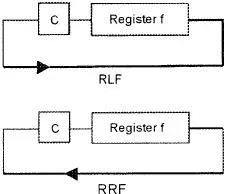
| RLF f,d | Contents of ‘f’ are rotated left one bit via the carry flag. If d=0 the result goes to W. Id=1, result goes back to f. See fig. below | C |
| SLEEP | Powerdown status bit PD is cleared, Timeout status bit TO is set. WDT and prescaler are cleared, oscillator stops and controller goes to sleep. | TO, PD |
| SUBLW k | W register subtracted from the number k, result goes into W reg. (2’s complement method) | C, DC, Z |
| SUBWF f,d | W register subtracted from the register f. If d=0 the result goes to W. If d=1 the result goes to f. (2’s complement method) | C, DC, Z |
| SWAPF f,d | Upper and lower nibbles of f are exchanged. If d=0 the result goes to W. If d=1 the result goes to f. | |
| XORLW k | W register contents XOR’ed with the number k, result goes into W reg. | Z |
| XORWF f,d | W register contents XOR’ed with the register f, if d=0 the result goes to W. If d=1 the result goes to f | Z |
Further reading
Bates, M. (2000) The Pic 16F84 Microcontroller. Arnold, London.
Bedford, M. (1996) Jubilee chips, Computer Shopper , December.
Bull, M. (1992) Students’ Guide to Programming Languages . Butterworth-Heinemann, Oxford.
Carthy, J. (1996) An Introduction to Assembly Language Programming and Computer Architecture . International Thomson Computer Press.
Crisp, J. (1996) Introduction to Fiber Optics . Butterworth-Heinemann, Oxford.
Diefendorff, K., Oehler, R. and Hochsprung, R. (1994) Evolution of PowerPC architecture, IEEE Micro , April.
Digital Equipment Corporation (1996) Hardware reference manual of the Digital Semiconductor 21164 Alpha Microprocessor.
Horowitz, P. and Hill, W. (1989) The Art of Electronics . Cambridge University Press, Cambridge.
Intel (1988) Microprocessor and Peripheral Handbook , Vol. 1.
Krause, J.K. (1997) A Chip off the old block, BYTE , November. Messmer, H.-P. (1995)
The Indispensable Pentium Book . Addison-Wesley, New York.
Читать дальшеИнтервал:
Закладка:
Похожие книги на «Introduction to Microprocessors and Microcontrollers»
Представляем Вашему вниманию похожие книги на «Introduction to Microprocessors and Microcontrollers» списком для выбора. Мы отобрали схожую по названию и смыслу литературу в надежде предоставить читателям больше вариантов отыскать новые, интересные, ещё непрочитанные произведения.


Обсуждение, отзывы о книге «Introduction to Microprocessors and Microcontrollers» и просто собственные мнения читателей. Оставьте ваши комментарии, напишите, что Вы думаете о произведении, его смысле или главных героях. Укажите что конкретно понравилось, а что нет, и почему Вы так считаете.