John Crisp - Introduction to Microprocessors and Microcontrollers
Здесь есть возможность читать онлайн «John Crisp - Introduction to Microprocessors and Microcontrollers» весь текст электронной книги совершенно бесплатно (целиком полную версию без сокращений). В некоторых случаях можно слушать аудио, скачать через торрент в формате fb2 и присутствует краткое содержание. Год выпуска: 2004, ISBN: 2004, Издательство: Elsevier, Жанр: Компьютерное железо, на английском языке. Описание произведения, (предисловие) а так же отзывы посетителей доступны на портале библиотеки ЛибКат.
- Название:Introduction to Microprocessors and Microcontrollers
- Автор:
- Издательство:Elsevier
- Жанр:
- Год:2004
- ISBN:0-7506-5989-0
- Рейтинг книги:3 / 5. Голосов: 1
-
Избранное:Добавить в избранное
- Отзывы:
-
Ваша оценка:
Introduction to Microprocessors and Microcontrollers: краткое содержание, описание и аннотация
Предлагаем к чтению аннотацию, описание, краткое содержание или предисловие (зависит от того, что написал сам автор книги «Introduction to Microprocessors and Microcontrollers»). Если вы не нашли необходимую информацию о книге — напишите в комментариях, мы постараемся отыскать её.
Introduction to Microprocessors and Microcontrollers — читать онлайн бесплатно полную книгу (весь текст) целиком
Ниже представлен текст книги, разбитый по страницам. Система сохранения места последней прочитанной страницы, позволяет с удобством читать онлайн бесплатно книгу «Introduction to Microprocessors and Microcontrollers», без необходимости каждый раз заново искать на чём Вы остановились. Поставьте закладку, и сможете в любой момент перейти на страницу, на которой закончили чтение.
Интервал:
Закладка:
Better than spraying ourselves with water, we can take a more hightech approach but how far to go in this direction depends on what is at stake. If we are going to handle a couple of cheap AND gates once a week, then only the simplest precaution is worthwhile. However, sitting on a production line plugging in microprocessors will make any precautions economic.
The simplest method is to have a conducting band clipped around your wrist with a lead going off to a ground (earthed) point. These wristbands are made of rubber into which carbon has been amalgamated to allow it to conduct slightly. As well as the wristband we can place a sheet of this rubber on the bench top and ground the bench. Such antistatic workstations are very effective. A word of warning. Do not make your own wrist strap from a length of copper wire. This offers a very low resistance and provides no protection against electrocution in the event of accidentally touching a power line.
At home, just avoid working on a plastic table or chair or wearing clothing made from man-made fibres. Natural materials like cotton, wool and untreated wood naturally absorb some water and are fairly safe. A nice wooden bench coated with polyurethane varnish is effectively a plastic bench and should be avoided.
Problems with plugs
Many plugs used between pieces of equipment have a large number of pins. Pulling one of these out with the power connected is going to disconnect some voltages before others. This can prove fatal for integrated circuits. Either all the supplies must be on, or all should be off so never plug or unplug anything with the power on. For the same reason, never remove or replace an integrated circuit with the power on.
Are the power supplies turned on? Do you need two supplies? If you are using two supplies, are they connected together to keep their voltages in step with one another? If a ground connection is required, is it connected?
Most power supplies have floating outputs. That means that a 5 V supply, for example, will have a 5 V difference between its two terminals but neither is connected to the ground potential. This means that if we connect the negative terminal to earth, as in Figure 18.1(a), the other terminal goes to +5 V. If, on the other hand, we make the connection shown in Figure 18.1(b), the other terminal will become –5 V.
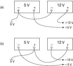
Figure 18.1 Connecting floating supplies
Have a look at the soldering if it is visible. It should be smooth and shiny. Any dull and craggy looking areas are suspect. If the integrated circuits are plugged into bases rather than being soldered, have a look to see if they have been inserted the right way round. Unfortunately, integrated circuit manufacturers take few precautions to prevent this type of error.
In most integrated circuits, the pins are numbered around the outside as shown in Figure 18.2. The position of pin 1 is always on the left-hand side of the end which has an indentation when viewed from the top as in Figure 18.2. When looking for the indentation don’t be mislead by a small circular mark where the plastic has been molded. The printed circuit board usually has either a number ‘1’ or a small square or other mark to indicate the position of the first pin.
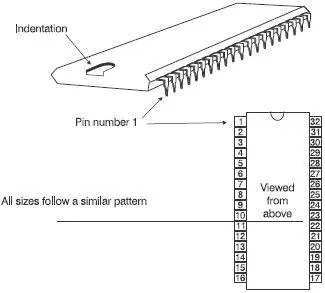
Figure 18.2 Pin numbering of ‘dual in line’ (DIL) chips
Figure 18.3 shows the pin grid array (PGA) layout. Notice that the letters skip from H to J because of the possible confusion between I and 1. The device determines the number of pins. The one shown happens to be the elderly Intel 80386. The Pentium has 21 pins along each side.
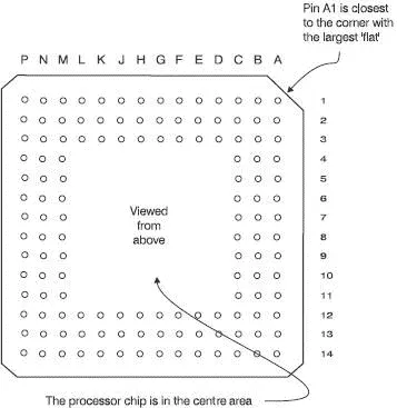
Figure 18.3 Pin numbering of Pin Grid Array (PGA)
Apart from the standard voltmeter and an oscilloscope the only other simple piece of gear that may be helpful is the logic probe. It is better than the average oscilloscope at detecting very short voltage spikes and is faster to work with than a voltmeter.
Logic probe
A logic probe is a simple instrument that has two power connections and the other is a conducting tip that can be touched on points of interest. The general layout is shown in Figure 18.4. There are three LEDs on it. The first two show the logic states 0 or 1 and the third one indicates the presence of a high frequency square-wave or a single, very short duration, pulse, called a ‘glitch’.
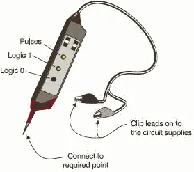
Figure 18.4 A logic probe
Simple tests to make with these pieces of test gear
We can check some of the voltages on the microprocessor pins. If possible, it is a good idea to check on the actual pins rather than the base into which it is plugged. Doing this ensures that the base connections are also OK. It would also find the bent pin shown in Figure 18.5.
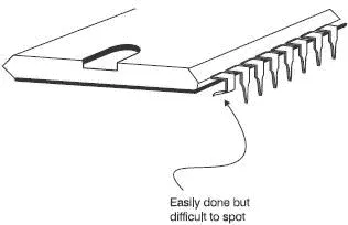
Figure 18.5 Pin bending not recommended
The likely pins that are worth checking are the ones carrying a dc voltage like the power supplies and the interrupts. It is worth keeping an eye on pins that should be at 0 V. When using a voltmeter, they can sometimes show 0 V when they are disconnected and floating. If you use your voltmeter to measure the voltage between the positive supply voltage and the suspect pin, it will still indicate 0 V showing that something is clearly amiss. A logic probe would not be fooled by a floating ‘zero’, it will not show a logic zero if it is floating.
The next job is to see if the microprocessor is running at all. We can do this by using the oscilloscope on a clock signal. Assuming that the clock signal is OK, we must next check that the microprocessor can follow an instruction and that the address and data bus are being read correctly.
A good check on the operation of the microprocessor can be arranged by getting it to do a simple repetitive program consisting of a permanent ‘no operation’ code. A no-operation code will instruct the microprocessor to do nothing except read the next instruction from the data bus by simply incrementing the value on the address bus. This new instruction will be another no-operation code and so the address bus will be continuously incremented. To provide a permanent no-op input we can solder or otherwise connect the required logic codes to the data bus. This is called hard-wiring the data bus. As the address bus counts up in binary the lowest address line will be switching rapidly between zero and one giving a square wave output.
If we look at Figure 18.6, we can see that line A1 is running at half the frequency of line A0. Similarly address line A2 has half the frequency of A1 and so on all the way along the address pins. If we connect an oscilloscope to each line in turn, the frequency should reduce steadily. Check for the halving of frequency on each address line and errors in wiring like short circuits between address lines will become apparent.
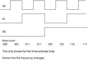
Figure 18.6 The address bus counts up in binary
Читать дальшеИнтервал:
Закладка:
Похожие книги на «Introduction to Microprocessors and Microcontrollers»
Представляем Вашему вниманию похожие книги на «Introduction to Microprocessors and Microcontrollers» списком для выбора. Мы отобрали схожую по названию и смыслу литературу в надежде предоставить читателям больше вариантов отыскать новые, интересные, ещё непрочитанные произведения.


Обсуждение, отзывы о книге «Introduction to Microprocessors and Microcontrollers» и просто собственные мнения читателей. Оставьте ваши комментарии, напишите, что Вы думаете о произведении, его смысле или главных героях. Укажите что конкретно понравилось, а что нет, и почему Вы так считаете.