John Crisp - Introduction to Microprocessors and Microcontrollers
Здесь есть возможность читать онлайн «John Crisp - Introduction to Microprocessors and Microcontrollers» весь текст электронной книги совершенно бесплатно (целиком полную версию без сокращений). В некоторых случаях можно слушать аудио, скачать через торрент в формате fb2 и присутствует краткое содержание. Год выпуска: 2004, ISBN: 2004, Издательство: Elsevier, Жанр: Компьютерное железо, на английском языке. Описание произведения, (предисловие) а так же отзывы посетителей доступны на портале библиотеки ЛибКат.
- Название:Introduction to Microprocessors and Microcontrollers
- Автор:
- Издательство:Elsevier
- Жанр:
- Год:2004
- ISBN:0-7506-5989-0
- Рейтинг книги:3 / 5. Голосов: 1
-
Избранное:Добавить в избранное
- Отзывы:
-
Ваша оценка:
Introduction to Microprocessors and Microcontrollers: краткое содержание, описание и аннотация
Предлагаем к чтению аннотацию, описание, краткое содержание или предисловие (зависит от того, что написал сам автор книги «Introduction to Microprocessors and Microcontrollers»). Если вы не нашли необходимую информацию о книге — напишите в комментариях, мы постараемся отыскать её.
Introduction to Microprocessors and Microcontrollers — читать онлайн бесплатно полную книгу (весь текст) целиком
Ниже представлен текст книги, разбитый по страницам. Система сохранения места последней прочитанной страницы, позволяет с удобством читать онлайн бесплатно книгу «Introduction to Microprocessors and Microcontrollers», без необходимости каждый раз заново искать на чём Вы остановились. Поставьте закладку, и сможете в любой момент перейти на страницу, на которой закончили чтение.
Интервал:
Закладка:
Address information, data and control signals have to be carried around inside the microprocessor as well as in the external system. We will therefore meet internal as well as external buses.
The signal on the data bus has only a very low power level and to be of use it must be amplified.
The first response was to put a series of amplifiers; one on the end of each of the connections on the data bus but this was soon superseded by a more sophisticated chip with more facilities. For example, if we wanted to send a signal to a printer at 1 ms intervals it would not be sensible to tie up the main processor with counting out these time intervals. It would be much better to tell the output chip to do its own timing and thus release the microprocessor for more important jobs.
The output devices have become quite complex and now go under a variety of names:
I/O controller – input/output controller
PIA – programmable interface adapter
VIA – versatile interface adapter
PIO – programmable input/output
PPI – programmable peripheral interface
…and many others.
Whatever name is given to the device, they are basically the same and are essential to any microprocessor-based system. An improved basic system is shown in Figure 7.5.
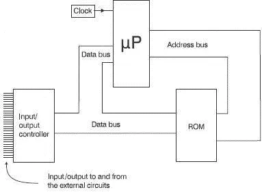
Figure 7.5 An input/output chip has been added
Apart from in the most minimal of circuits, some RAM is needed. Even if the microprocessor-based system is controlling an oven, we still need the facility to vary the instructions to change the temperature, the time cycle, the fan speed etc., so some RAM must be added. Some microprocessors have a small amount of RAM included internally, enough for this sort of system to work but still quite limited. If we add some external RAM, the microprocessor is controlling the operation of three chips: ROM, RAM and I/O. To control the flow of information it needs to send chip select and read/write information along the control bus.
Read/write signals tell the RAM and the I/O chip whether they have to read, i.e. accept information from the data bus or to write information onto the data bus.
Chip select is the on/off switch for each of the chips and we have to be very careful to ensure that only one set of information is being connected to the data bus at one time.
If a ROM chip were to be putting a binary 0 onto one of the data bus connections and, at the same time, another ROM or a RAM chip was applying a binary 1, there would be a disagreement between the two chips. What would happen? It is sad but the likely outcome is a fight to the finish with one or other of the chips being condemned to the waste bin.
To prevent this from happening, an address decoder circuit samples the address bus and selects the appropriate chip. If the microprocessor wishes to send some data to the RAM chip, it applies a suitable address to the address bus that is applied to the ROM, RAM and the I/O controller but there are no problems at the moment since all these chips are switched off. The address decoder applies the inputs from the address bus to an array of logic gates that have been organized to comply with the memory map of the system. The output from the address decoder then switches the RAM chip on and the ROM and I/O chips off. The design of the address decoder can be modified to control any number of external chips in the system. An upgraded system is shown in Figure 7.6.
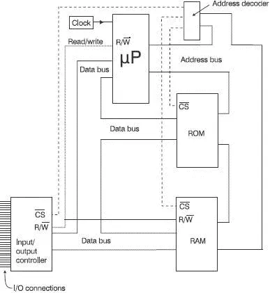
Figure 7.6 A complete microprocessor system
To demonstrate its operation we can ask it to perform a simple task. Instruction: Send the number 25H which is in the ROM and store it in the RAM at address 2500H. This is what happens – follow the action on Figure 7.6.
1 The microprocessor has to collect the instruction from an address in ROM. It does this by putting the address onto the address bus.
2 The address is applied to the ROM and the RAM as well as the address decoder. This will not cause any problems because all the chip selects will be switched off at the moment. When the logic gates within the address decoder responds to the input from the address bus the result will be that the ROM is switched on and the other two are kept off.
3 Switching on the ROM will mean that it takes in the address from the address bus. Inside the ROM chip, the row and column decoders activate one of the memory locations and the binary number stored at that location is placed on the data bus by switching on the tri-state buffers. As soon as the information is read, the chip select will switch the ROM chip off.
4 The information which is now on the data bus is read by the microprocessor. It is an instruction which can be interpreted as ‘go to address F600H and read the number that is stored in that address’.
5 In response to this instruction, the microprocessor puts the address F600H onto the address bus.
6 The address decoder applies this number to its logic gates and this results in the chip select of the ROM chip being switched on again. The ROM chip accepts the address F600H into its row and column decoders and then puts the number 25H onto the data bus.
7 This number is stored temporarily in the microprocessor.
8 The microprocessor then puts the number 2500H onto the address bus and the address decoder puts a signal on the chip select of the RAM chip to switch it on. It then sends a logic 1 on the read/write line. The RAM is switched on and it is told to read the data on the data bus. The read/write line goes to the I/O chip as well but again, this causes no problem because its chip select line is keeping it switched off.
The number 25 is now safely stored in the RAM chip and will remain there until it is over-written with new information or the power is switched off.
We have seen in Chapter 6 that the number of locations that can be addressed is 2 n where n is the number of address lines. By feeding the numbers into our calculators we can see that the relationship between lines and locations is as shown in Table 7.1.
Table 7.1 Larger memories need more address lines
| Number of address lines | Number of locations | Number of address lines | Number of locations | Number of address lines | Number of locations |
|---|---|---|---|---|---|
| 1 | 2 | 13 | 8k | 25 | 32M |
| 2 | 4 | 14 | 16k | 26 | 64M |
| 3 | 8 | 15 | 32k | 27 | 128M |
| 4 | 16 | 16 | 64k | 28 | 256M |
| 5 | 32 | 17 | 128k | 29 | 512M |
| 6 | 64 | 18 | 256k | 30 | 1024M=1G |
| 7 | 128 | 19 | 512k | 31 | 2G |
| 8 | 256 | 20 | 1024k=1M | 32 | 4G |
| 9 | 512 | 21 | 2M | 33 | 8G |
| 10 | 1024 = 1k | 22 | 4M | 34 | 16G |
| 11 | 2k | 23 | 8M | 35 | 32G |
| 12 | 4k | 24 | 16M | 36 | 64G |
We can also use this table to identify the number of lines needed to access a known number of address locations. For example, if we wanted to access 700 locations, we can see that 9 lines could access 512 locations which is too few. Therefore, we would have to go to 10 lines which would actually give access to 1024 locations. The ‘real’ answer of 9.45 is not sensible because we cannot have 0.45 of a connecting wire so if 9 is not enough, it will have to be 10. For those who like to see the calculations, the mathematical result is given by:
Читать дальшеИнтервал:
Закладка:
Похожие книги на «Introduction to Microprocessors and Microcontrollers»
Представляем Вашему вниманию похожие книги на «Introduction to Microprocessors and Microcontrollers» списком для выбора. Мы отобрали схожую по названию и смыслу литературу в надежде предоставить читателям больше вариантов отыскать новые, интересные, ещё непрочитанные произведения.


Обсуждение, отзывы о книге «Introduction to Microprocessors and Microcontrollers» и просто собственные мнения читателей. Оставьте ваши комментарии, напишите, что Вы думаете о произведении, его смысле или главных героях. Укажите что конкретно понравилось, а что нет, и почему Вы так считаете.