John Crisp - Introduction to Microprocessors and Microcontrollers
Здесь есть возможность читать онлайн «John Crisp - Introduction to Microprocessors and Microcontrollers» весь текст электронной книги совершенно бесплатно (целиком полную версию без сокращений). В некоторых случаях можно слушать аудио, скачать через торрент в формате fb2 и присутствует краткое содержание. Год выпуска: 2004, ISBN: 2004, Издательство: Elsevier, Жанр: Компьютерное железо, на английском языке. Описание произведения, (предисловие) а так же отзывы посетителей доступны на портале библиотеки ЛибКат.
- Название:Introduction to Microprocessors and Microcontrollers
- Автор:
- Издательство:Elsevier
- Жанр:
- Год:2004
- ISBN:0-7506-5989-0
- Рейтинг книги:3 / 5. Голосов: 1
-
Избранное:Добавить в избранное
- Отзывы:
-
Ваша оценка:
Introduction to Microprocessors and Microcontrollers: краткое содержание, описание и аннотация
Предлагаем к чтению аннотацию, описание, краткое содержание или предисловие (зависит от того, что написал сам автор книги «Introduction to Microprocessors and Microcontrollers»). Если вы не нашли необходимую информацию о книге — напишите в комментариях, мы постараемся отыскать её.
Introduction to Microprocessors and Microcontrollers — читать онлайн бесплатно полную книгу (весь текст) целиком
Ниже представлен текст книги, разбитый по страницам. Система сохранения места последней прочитанной страницы, позволяет с удобством читать онлайн бесплатно книгу «Introduction to Microprocessors and Microcontrollers», без необходимости каждый раз заново искать на чём Вы остановились. Поставьте закладку, и сможете в любой момент перейти на страницу, на которой закончили чтение.
Интервал:
Закладка:
To use a cell, the row containing the cell must be selected and the column containing the cell must also be activated. The shaded cell in Figure 6.15 has the address 0110 which means that it is in row 01 and in column 10.
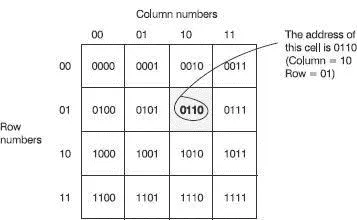
Figure 6.15 Selecting a memory location
To access this cell we need to apply the binary address to the row and column decoders. When the address 0110 is applied, the first half of the address, 01, is applied to the row decoder and the second half of the address is applied to the column decoder. A decoder circuit is a small logic circuit that, when fed with the address of the location, is able to switch on the appropriate row and column. The maximum number of locations that can be addressed will depend on the number of bits in the address. We have already seen that a 4-bit address can access 16 locations. This was because 2 4=16, so, generally 2 n = number of locations where n is the number of bits in the address. To take a more realistic example, if we had 20 address lines we would have 2 20=1 048 576 or 1 Meg locations.
Ram chips can be designed in two different forms which we call static RAM (SRAM) and dynamic RAM (DRAM), as seen in Figure 6.16.
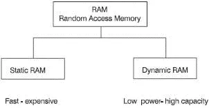
Figure 6.16 The two types of RAM
Static RAM
These are constructed of flip-flops. The problem with the flip-flop is that it draws current all the time. Therefore, it tends to get rather warm and, on a single chip, the components cannot be packed together very tightly. The benefit is that they are very fast and are used where speed of access is important. Static RAM is often called SRAM.
Dynamic RAM
These store the information in capacitors, which are small components that store an electrical charge in the form of static electricity. They are called ‘dynamic’ owing to one of its drawbacks. In use, the electricity stored in each capacitor leaks away because of the imperfect insulation. So, after a little while the charge has to be replaced otherwise the DRAM will be empty and all the stored information will be lost. This replacing is called ‘refreshing’ and has to be performed at intervals of about 2 ms by a DRAM control circuit. To prevent any interference with the operation of the microprocessor system, the refreshing is done in the background whenever the DRAM is not being used.
Once the static charge is stored, no further current is required (except for refreshing), therefore less heat is being generated internally and we can pack more memory into a given space. We say it has a high packing density.
A memory contains a number of cells or registers that, themselves store a number of bits. In Figure 6.14, we saw a really simple memory with 16 locations, each of which could store between 1, 4 or 8 bits. The memory organization is always quoted as ‘number of locations x bits stored in each’ so this memory would have an organization of anywhere between 16×1, 16×4 or 16×8.
Static RAMs usually store 8 bits in each location so a typical chip size would be 131 072×8 giving a total storage capacity of 1 048 576 bits. This is often referred to as 128 K×8.
Dynamic RAMs store either 1 or 4 bits in each location. One bit in each is very popular, so a typical chip organization would be 1 048 576×1 which, as we can see, would actually hold the same total number of bits as the example SRAM – it’s just the organization that has been changed.
All ROMs are used to store information on a more-or-less permanent basis. In use, the ROM can be read but new information cannot be stored in it. In other words, we cannot write to it (see Figure 6.17).
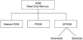
Figure 6.17 Three types of ROM
Masked ROM
A masked ROM is manufactured to our specification and cannot be changed. We must be very sure that the information is correct before it is made otherwise it all goes in the waste bin and the person responsible is looking for a new job. The initial cost is necessarily high due to the expense of the tooling required. It is only worthwhile if at least a few thousand identical chips are required (see Figure 6.18).
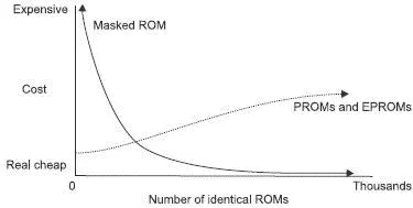
Figure 6.18 The economics of ROM choice
Programmable ROM (PROM)
This chip is supplied with all the data held at zero by means of small internal fuses. When one of the fuses is blown, the associated bit changes from 0 to 1. To blow the fuses a piece of programming equipment is needed. This equipment can be purchased quite cheaply if only one PROM is to be programmed at a time. If a larger throughput is needed then this will inevitably increase the cost of the equipment. Once the fuse is blown, it cannot be repaired so if you make a mistake, the chip is wasted.
The ROM is useful for low volume production because the initial costs are much lower than the masked ROM but you do have to program them yourself.
Erasable programmable ROM (EPROM)
As the name would suggest, this chip allows us to program it, then change our mind and try again. To erase the data there are two methods – ultraviolet light or electrical voltage pulses. EPROMs are ideal for prototyping since it is so easy to change the data to make modifications.
The UVEPROM
The chip is bombarded with ultraviolet light via a transparent window on the chip. A specially constructed EPROM eraser provides the light. We pop the chip in, close the lid and switch on the timer. After a few minutes, the data is erased. When erased, all the data output is set to 1. We then put the chip into an EPROM programmer, usually the same piece of gear that was used to program the PROM. We can feed in the new data and within a couple of minutes, we have finished the process.
They can be erased and reprogrammed about 700 times before they become increasingly reluctant to erase and their life is over. Once programmed, the data is safe for about seven years. For long term storage, it is best to reload them or, better still, use a masked ROM if available.
A safety note: be extremely careful not to expose your eyes to the ultraviolet light from the eraser. The wavelength of 253.7 nm is very dangerous.
Electrically erasable programmable ROM (EEPROM)
This chip uses electrical voltage pulses as inputs to clear the previous data and is then reprogrammed in the same way as the UVEPROM. It has the added advantage that individual parts of the data can be reprogrammed without deleting everything first as is the case with the ultraviolet version. EEPROM can be found as serial access (SAM), as well as the more usual random access.
The reprogramming can be done while installed in the microprocessor-based system. It does not need a separate programmer. Their disadvantage is that they are slow to program and have a limited number of reprogramming cycles.
Figure 6.19 shows the pin-out diagram for a 1 Mb (1 048 576 bits) EPROM with an organization of 131 072×8 bits.
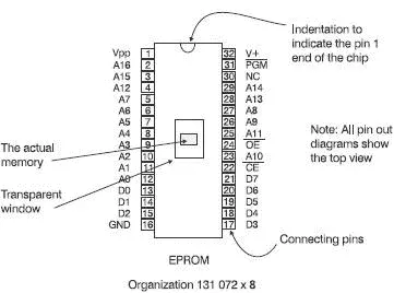
Figure 6.19 Pin out diagram of an EPROM
Читать дальшеИнтервал:
Закладка:
Похожие книги на «Introduction to Microprocessors and Microcontrollers»
Представляем Вашему вниманию похожие книги на «Introduction to Microprocessors and Microcontrollers» списком для выбора. Мы отобрали схожую по названию и смыслу литературу в надежде предоставить читателям больше вариантов отыскать новые, интересные, ещё непрочитанные произведения.


Обсуждение, отзывы о книге «Introduction to Microprocessors and Microcontrollers» и просто собственные мнения читателей. Оставьте ваши комментарии, напишите, что Вы думаете о произведении, его смысле или главных героях. Укажите что конкретно понравилось, а что нет, и почему Вы так считаете.