John Crisp - Introduction to Microprocessors and Microcontrollers
Здесь есть возможность читать онлайн «John Crisp - Introduction to Microprocessors and Microcontrollers» весь текст электронной книги совершенно бесплатно (целиком полную версию без сокращений). В некоторых случаях можно слушать аудио, скачать через торрент в формате fb2 и присутствует краткое содержание. Год выпуска: 2004, ISBN: 2004, Издательство: Elsevier, Жанр: Компьютерное железо, на английском языке. Описание произведения, (предисловие) а так же отзывы посетителей доступны на портале библиотеки ЛибКат.
- Название:Introduction to Microprocessors and Microcontrollers
- Автор:
- Издательство:Elsevier
- Жанр:
- Год:2004
- ISBN:0-7506-5989-0
- Рейтинг книги:3 / 5. Голосов: 1
-
Избранное:Добавить в избранное
- Отзывы:
-
Ваша оценка:
Introduction to Microprocessors and Microcontrollers: краткое содержание, описание и аннотация
Предлагаем к чтению аннотацию, описание, краткое содержание или предисловие (зависит от того, что написал сам автор книги «Introduction to Microprocessors and Microcontrollers»). Если вы не нашли необходимую информацию о книге — напишите в комментариях, мы постараемся отыскать её.
Introduction to Microprocessors and Microcontrollers — читать онлайн бесплатно полную книгу (весь текст) целиком
Ниже представлен текст книги, разбитый по страницам. Система сохранения места последней прочитанной страницы, позволяет с удобством читать онлайн бесплатно книгу «Introduction to Microprocessors and Microcontrollers», без необходимости каждый раз заново искать на чём Вы остановились. Поставьте закладку, и сможете в любой момент перейти на страницу, на которой закончили чтение.
Интервал:
Закладка:
An AND gate is any circuit that gives a logic (or binary) 1 if (and only if) every input to the circuit is at logic 1. So in microprocessors, with only two inputs, it is easier to say that it gives a 1 out if both of the inputs is at logic 1. The symbols for the AND gate are shown in Figure 5.4.
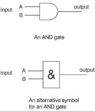
Figure 5.4 Symbols for an AND gate
The truth table in Figure 5.5 has four rows to cover all the possible combinations of inputs.
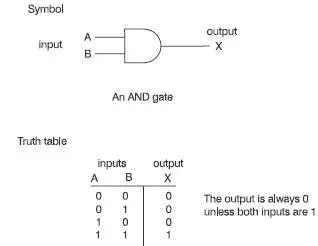
Figure 5.5 The truth table for an AND gate
What is the point of an AND gate?
We often meet an AND gate without realizing it. When we climb into an elevator the door must be closed AND the floor button pressed before the motor will start. This is an AND gate in action. In a microprocessor, groups of AND gates are used to handle pairs of inputs at the same time just like we did with the NOT gates. For convenience we usually use hex numbers to describe groups of inputs and outputs but remember it’s all really happening in binary.
Unless we appreciate that the hex numbers are really just groups of ones and zeros, it may seem odd to talk about putting numbers through AND gates. Figure 5.6 may make it (a little) clearer. In this figure, we have used hex inputs of 37H and 5BH giving a result of 13H. Note that the AND gate does not add numbers.
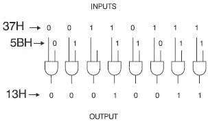
Figure 5.6 An AND gate in action
A little extra bit
In data books and manuals, the AND function is abbreviated to a dot like a period (full-stop). So, if an AND gate had two inputs called A and B and an output called X, then we could write X = A·B
Sometimes it is further simplified to X = AB
Very occasionally we come across a symbol ∧ so we can write X=A∧B.
The word NAND is just a fancy contraction of NOT and AND. The NAND gate is just an AND gate followed by a NOT gate so all the outputs shown in the AND truth table are just inverted by the NOT gate.
On a diagram, this combination is indicated by putting a small circle on the end of the symbol. The symbol and truth table are shown in Figure 5.7.
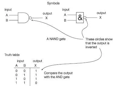
Figure 5.7 The truth table for a NAND gate
It is better not to make a big effort to learn the NAND gate. Just remember that it’s the same as the AND gate except the output has been inverted by the NOT gate that has been added internally. The symbol has a line over the top to indicate the added NOT function. A two input NAND could be written as X=  or X=
or X=  or very occasionally X=
  .
.
This follows on nicely from the AND gate. The OR gate gives a logic one at its output if either (or both) of the inputs is at a logic one. Just like the AND gate, the OR gate can have as many inputs as we wish but in a microprocessor, we only use two input versions. Its symbols and truth table are shown in Figures 5.8 and 5.9.
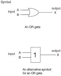
Figure 5.8 Symbols for an OR gate
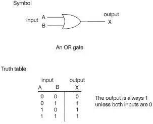
Figure 5.9 The truth table for an OR gate
Another extra bit
The OR function can be written as + or sometimes ∨. So, if an OR gate had two inputs called A and B and an output called X, then we could write X=A+B or X=A∨B. Don’t mistake this + sign as ‘plus’ as in addition 3+4=7.
As we would expect, this is just the same as the OR gate except for the NOT gate added to the output. The symbol has the inversion line over it to give X=  or
or  (see Figure 5.10).
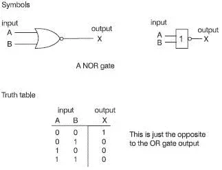
Figure 5.10 The NOR gate
This is called the Exclusive-OR gate, which is abbreviated to XOR or EOR. Here are two examples of everyday English, both using the word ‘or’.
We get into an elevator and the operator says to us ‘Do you want to go up or down?’ We have a choice, we can decide to go up or we can go down. We have two possible answers – ‘up’ or ‘down’.
On the way home we buy a burger. We are asked ‘Do you want ketchup or mustard?’ This time we could answer ‘ketchup’ or ‘mustard’ or we could say ‘both’.
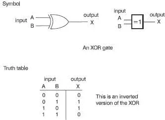
Figure 5.11 The XOR or difference gate
This is a fine example of how we can make something which is really easy appear difficult. The word ‘or’ in English has two different meanings which can be referred to as exclusive and inclusive. The first example used the exclusive ‘or’ because we could have one or the other but not both . The second situation uses the inclusive ‘or’ because we could have one or the other or both. We use both meanings everyday and understand them so well that we know automatically which one is meant.
In the XOR gate the output is a logic one if either input is a logic 1 but not both . Only two-input XOR gates are manufactured, whether for use in a microprocessor or not (see Figure 5.11).
To look at it in another way, the output from an XOR is a logic one if the two inputs are different. For this reason, it is often called a ‘Difference’ gate.
The electronic padlock
When we want to take some money out of our bank account we can go to the money machine and pop our card in. It then asks us to key in our code number which is usually a four-digit number. If the number is correct, we have access to our account.
In the background is a microprocessor with two useful attributes:
1 Microprocessors are very good at spotting whether a number is zero or not.
2 They contain a series of XOR gates.
So how can it check my number? One easy method is to compare our keyed-in number with the number read from the magnetic strip on the back of the card. Each of our code numbers is treated as a hex number and converted to a four-bit binary number. This results in one 16-bit binary number from the keyboard and another from the magnetic strip on the card, which now have to be compared.
Inside the microprocessor are 16 XOR gates each with two inputs – one from the card and one from the keyboard. Every time the bits coincide, whether they are both zeros or both ones, the output will be a zero.
Читать дальшеИнтервал:
Закладка:
Похожие книги на «Introduction to Microprocessors and Microcontrollers»
Представляем Вашему вниманию похожие книги на «Introduction to Microprocessors and Microcontrollers» списком для выбора. Мы отобрали схожую по названию и смыслу литературу в надежде предоставить читателям больше вариантов отыскать новые, интересные, ещё непрочитанные произведения.


Обсуждение, отзывы о книге «Introduction to Microprocessors and Microcontrollers» и просто собственные мнения читателей. Оставьте ваши комментарии, напишите, что Вы думаете о произведении, его смысле или главных героях. Укажите что конкретно понравилось, а что нет, и почему Вы так считаете.