John Crisp - Introduction to Microprocessors and Microcontrollers
Здесь есть возможность читать онлайн «John Crisp - Introduction to Microprocessors and Microcontrollers» весь текст электронной книги совершенно бесплатно (целиком полную версию без сокращений). В некоторых случаях можно слушать аудио, скачать через торрент в формате fb2 и присутствует краткое содержание. Год выпуска: 2004, ISBN: 2004, Издательство: Elsevier, Жанр: Компьютерное железо, на английском языке. Описание произведения, (предисловие) а так же отзывы посетителей доступны на портале библиотеки ЛибКат.
- Название:Introduction to Microprocessors and Microcontrollers
- Автор:
- Издательство:Elsevier
- Жанр:
- Год:2004
- ISBN:0-7506-5989-0
- Рейтинг книги:3 / 5. Голосов: 1
-
Избранное:Добавить в избранное
- Отзывы:
-
Ваша оценка:
Introduction to Microprocessors and Microcontrollers: краткое содержание, описание и аннотация
Предлагаем к чтению аннотацию, описание, краткое содержание или предисловие (зависит от того, что написал сам автор книги «Introduction to Microprocessors and Microcontrollers»). Если вы не нашли необходимую информацию о книге — напишите в комментариях, мы постараемся отыскать её.
Introduction to Microprocessors and Microcontrollers — читать онлайн бесплатно полную книгу (весь текст) целиком
Ниже представлен текст книги, разбитый по страницам. Система сохранения места последней прочитанной страницы, позволяет с удобством читать онлайн бесплатно книгу «Introduction to Microprocessors and Microcontrollers», без необходимости каждый раз заново искать на чём Вы остановились. Поставьте закладку, и сможете в любой момент перейти на страницу, на которой закончили чтение.
Интервал:
Закладка:
IBM are building (2002) a new super computer employing a million microprocessors. The Blue Gene project will result in a computer running at a speed of over a thousand million million operations per second (1 petaflop). This is a thousand times faster that the Intel 1998 world speed record or about two million times faster than the current top-of-the-range desktop computers.
If we need more accuracy, an alternative method is to increase the number of bits that can be used to store the number from 32 (singleprecision) to 64 (double-precision). If this extra storage space is devoted to increasing the mantissa bits, then the accuracy is increased significantly.
Binary coded decimal numbers are very simple. Each decimal digit is converted to binary and written as a 4-bit or 8-bit binary number. The number 5 would be written as 0101 2or 00000101 2. So far, this is the same as ‘ordinary’ binary but the change occurs when we have more digits.
Consider the number 25 10. In regular binary this would convert to 11001 2. Alternatively, we could convert each digit separately to 4-bit or 8-bit numbers:
2 = 0010 2or 0000 0010 2
5 = 0101 2or 0000 0101 2
Putting these together, 25 10could be written using the 4-bit numbers as 0010 0101 2. This uses one byte and is called Packed BCD. Alternatively, we could use the 8-bit formats and express 25 10as 0000 0010 0000 0101 2and would now use two bytes. This is called Unpacked BCD.
There are two disadvantages. Firstly, many numbers are of increased length after converting to BCD, particularly so if we use unpacked BCD or the numbers are very large like 25×10 75. In addition, arithmetic is much more difficult although, generally, microprocessors do have the ability to handle them.
The advantage becomes apparent when the microprocessor is controlling an external device like digits on displays at a filling station or accepting inputs from a keyboard. The coding is simple and does not involve the conversion of the numbers to binary.
Overall
Arithmetic → use binary
Inputting and outputting numbers → use BCD
In each case, choose the best option.
1 The number –35 10, when expressed as an 8-bit binary number in two’s complement form, is:
(a) 00100011.
(b) 1111011101.
(c) 11011101.
(d) 00110101.
2 The number 7 10converted to an unpacked BCD format would be written as:
(a) 1110 0000.
(b) 7H.
(c) 0000 0111.
(d) 0111.
3 The signed magnitude number 11001100 2is equivalent to:
(a) –76 10.
(b) 204 10.
(c) CCH.
(d) 1212 10.
4 In the number 0.5×10 24the number:
(a) 10 is the mantissa.
(b) 24 is the exponent.
(c) 0 is the sign bit.
(d) 5 is the radix.
5 A signed magnitude number that has a figure:
(a) zero as the msb is a negative number.
(b) one as the lsb is a negative number.
(c) one as the msb is a negative number.
(d) zero as the lsb is a negative number.
5. An introduction to logic gates and their uses
In the last chapter the binary values zero and one are represented by two different voltages. Binary zero is a voltage close to 0 V and binary one by a voltage close to +5 V (some logic circuits use other voltage levels but this is a popular value and will serve as an example). A gate is a simple electronic circuit that has a single output voltage that corresponds to one of the two binary values. These gates are often referred to as ‘logic gates’ and the output voltages as ‘logic 0’ or ‘logic 1’ instead of binary 0 and 1. The distinction is just in the name. If you were to ask a mathematician or a computer programmer, they will refer to the outputs as binary values but an electronics engineer will call them logic levels. It really doesn’t matter.
We connect one or more voltages to the input of the gate. These input voltages are either logic 0 or logic 1 levels. The logic gate looks at the input voltages and ‘decides’, depending on its design, what voltage to produce at the output of the circuit.
There are only four basic designs of gate. They are called the NOT gate, the AND gate, the OR gate and the XOR gate. Notice how we use capital letters for the names of the gates otherwise we can finish up with some almost indecipherable sentences. Not not or and not and or not…
A little reminder before we start. Logic gates are clever little chaps but they are not magic. Just like any other electronic circuit, they need power supplies to make them work. Now, because all gates and microprocessors need power supplies, we tend to assume that everyone knows that. You will notice that power supplies are not shown in any of the diagrams in this chapter but that doesn’t mean that they are not there!
We will explore these gates now, starting from the simplest.
It has only one input and performs a very simple function. It simply reverses the binary value. If we put a logic 1 into it, we get a logic 0 at the output. Similarly, a 0 at the input gives a 1 at the output. On a diagram, we represent a NOT gate by a symbol as shown in Figure 5.1.
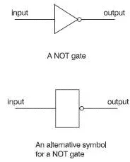
Figure 5.1 Symbols for a NOT gate
This is an alternative to the wordy description of how a gate works. It simply lists all the possible inputs to the gate together with the corresponding outputs. The truth table for a NOT gate is really easy. There are only two possible inputs: 0 and 1 as we can see in Figure 5.2.
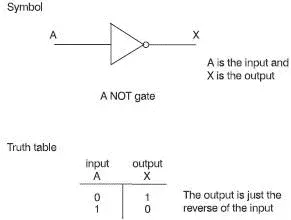
Figure 5.2 The truth table for a NOT gate
So, how is it used in the microprocessor?
The truth table only shows what happens to a single bit but in the microprocessor we may want to use a NOT gate to invert a hex number like A4H. In this case the hex number is first converted to an 8-bit binary number. This process is not performed by the microprocessor but by other external circuits. By the time it reaches the microprocessor it has been converted to the binary equivalent of 10100100 2.
The NOT gate has only one input so, to handle an 8-bit binary word, we will need eight NOT gates. Now it becomes much easier. Each NOT gate inverts just one of the bits and all the outputs are grouped together to form a new hex number. See how it works in Figure 5.3. The result was the hex number 5BH. This is curious. If we add A4H to this result of 5BH we get FFH or all ‘ones’ in binary, 11111111 2. There was nothing special about the number A4H. It happens with any pair of numbers generated by NOT gates. Why is this? Figure 5.3 gives a clue.

Figure 5.3 Inverting a hex number
A little extra bit
We can show an inversion by drawing a line over the top. In Figure 5.2 the input was given the letter A and the output was shown as X. We could say: X=  .
.
Unlike the NOT gate, an AND gate has more than one input. In fact we can have as many inputs as we like but the good news is that in microprocessors only two inputs are used. This simplifies the symbols and the truth tables considerably.
Читать дальшеИнтервал:
Закладка:
Похожие книги на «Introduction to Microprocessors and Microcontrollers»
Представляем Вашему вниманию похожие книги на «Introduction to Microprocessors and Microcontrollers» списком для выбора. Мы отобрали схожую по названию и смыслу литературу в надежде предоставить читателям больше вариантов отыскать новые, интересные, ещё непрочитанные произведения.


Обсуждение, отзывы о книге «Introduction to Microprocessors and Microcontrollers» и просто собственные мнения читателей. Оставьте ваши комментарии, напишите, что Вы думаете о произведении, его смысле или главных героях. Укажите что конкретно понравилось, а что нет, и почему Вы так считаете.