Geoff Klempner - Handbook of Large Hydro Generators

Здесь есть возможность читать онлайн «Geoff Klempner - Handbook of Large Hydro Generators» — ознакомительный отрывок электронной книги совершенно бесплатно, а после прочтения отрывка купить полную версию. В некоторых случаях можно слушать аудио, скачать через торрент в формате fb2 и присутствует краткое содержание. Жанр: unrecognised, на английском языке. Описание произведения, (предисловие) а так же отзывы посетителей доступны на портале библиотеки ЛибКат.

Handbook of Large Hydro Generators: краткое содержание, описание и аннотация

Предлагаем к чтению аннотацию, описание, краткое содержание или предисловие (зависит от того, что написал сам автор книги «Handbook of Large Hydro Generators»). Если вы не нашли необходимую информацию о книге — напишите в комментариях, мы постараемся отыскать её.

This book offers comprehensive coverage of the operation and maintenance of large hydro generators This book is a practical handbook for engineers and maintenance staff responsible for the upkeep of large salient-pole hydro generators used in electric power plants. Focusing on the physics and maintenance of large vertical salient pole generators, it offers readers real-world experience, problem description, and solutions, while teaching them about the design, modernization, inspections, maintenance, and operation of salient pole machines.
Handbook of Large Hydro Generators: Operation and Maintenance Written with a machine operator and inspector in mind,
:
Instructs readers how to perform complete machine inspections, understand what they are doing, and find solutions for any problems encountered Includes real-life, practical, field experiences so that readers can familiarize themselves with aspects of machine operation, maintenance, and solutions to common problems Benefits experienced and new power plant operators, generator design engineers and operations engineers. Is authored by industry experts who participated in the writing and maintenance of IEEE standards (IEEE C50.12 and C50.13) on the subject 
is an ideal resource for scientists and engineers whose research interest is in electromagnetic and energy conversion. It is also an excellent book for senior undergraduate and graduate students majoring in energy generation, and generator operation and maintenance.
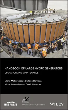
Handbook of Large Hydro Generators — читать онлайн ознакомительный отрывок

Ниже представлен текст книги, разбитый по страницам. Система сохранения места последней прочитанной страницы, позволяет с удобством читать онлайн бесплатно книгу «Handbook of Large Hydro Generators», без необходимости каждый раз заново искать на чём Вы остановились. Поставьте закладку, и сможете в любой момент перейти на страницу, на которой закончили чтение.

Тёмная тема
Сбросить

Интервал:

Закладка:

Сделать

2 Chapter 2 Figure 2.1-1 Cross section of core showing inter‐laminar damage and the eddy... Figure 2.1-2 Inter‐laminar insulation reduces eddy current losses in the ste... Figure 2.1-3 Laminated‐core eddy‐current loss as percentage of full‐block lo... Figure 2.1-4 Stator core segment described. Figure 2.1-5 Showing the U shaped or “hairpin” coil. Figure 2.1-6 Lamination stacking in the stator, also showing the conventiona... Figure 2.1-7 Heavy lamination segment with I‐shaped blocks (radial duct) – r... Figure 2.1-8 Shows double dovetail design that prevents core buckling. Figure 2.1-9 Core‐to‐keybar mounting arrangement in the stator frame. Shim l... Figure 2.1-10 Shows another arrangement for the core bolt. Figure 2.1-11 For demonstration purposes this figure shows an insulating bus... Figure 2.1-12 Showing the vent lamination with the hole to accommodate the b... Figure 2.1-13 Shows compression washer assembly. Figure 2.1-14 Shows keybar and core clamping bolt as one piece with threaded... Figure 2.1-15 76 MVA newly piled stator core showing the clamping finger ass... Figure 2.1-16 86 MVA newly piled stator core showing the first packet with s... Figure 2.1-17 Shows finger plate installation with adjustable fulcrum points... Figure 2.2-1 Shows outside part of stator frame showing the wrapper plate an... Figure 2.2-2 Typical soleplate positioned in the foundation awaiting final s... Figure 2.2-3 Shows another style of soleplate with double “J or T” hooks. Figure 2.3-1 Four pole generator flux pattern. Figure 2.3-2 Flux distribution and flux density at no load obtained by FE si... Figure 2.3-3 Flux distribution and flux density at rated load obtained by FE... Figure 2.3-4 Flux distribution and flux density during sudden short circuit ... Figure 2.3-5 Shows the flux distribution in the over‐excited mode with field... Figure 2.3-6 Shows the flux density in the over‐excited mode with field curr... Figure 2.3-7 Shows the flux distribution in the under excited mode with fiel... Figure 2.3-8 Shows the flux density in the under excited mode with field cur... Figure 2.7-1 Typical multi‐turn coil strand configurations. Figure 2.7-2 Typical single turn Roebel bar configuration. Figure 2.7-3 Cross section of stator bar in the stator slot. Figure 2.7-4 Cross section of a stator multi‐turn coil in the stator slot. Figure 2.7-5 Shows a two turn bar in the stator slot (teeth are adjacent to ... Figure 2.7-6 Stator endwinding showing reversing group jumper connection on ... Figure 2.7-7 Stator endwinding showing reversing group jumper connections on... Figure 2.7-8 Showing reduced eddy current losses with individual strands of ... Figure 2.7-9 Individual strand cross section to reduce losses from right to ... Figure 2.7-10 Looping of a coil with inverted turn. Figure 2.7-11 Roebel transposition 3D view. Figure 2.7-12 Roebel bar principle. Figure 2.7-13 Temperature profile of a double‐stack stator bar with separate... Figure 2.7-14 Cross Roebel transposition‐temperature profile of a double‐sta... Figure 2.7-15 Cross Roebel transposition – temperature profile of a double s... Figure 2.7-16 Shows a 3D representation of a typical water cooled stator bar... Figure 2.7-17 Direct cooled stator winding (rotor poles removed). Figure 2.7-18 Shows the black semiconducting material and the grey Silicon C... Figure 2.7-19 Flat side‐packing (top) and ripple spring (bottom) with semico... Figure 2.7-20 Shows stand up view of Figure 2.7-19 to illustrate the ripple ... Figure 2.8-1 Typical packing material and wedge assemblies. Figure 2.8-2 Various types of wedge assemblies. Figure 2.8-3 Shows core packet and fretting at the interface of wedge groove... Figure 2.8-4 Shows minimal damage to wedge groove after cleaning. Figure 2.9-1 Stator endwinding support system for a bar winding. Figure 2.9-2 Stator endwinding support system for a multi‐turn coil. Figure 2.10-1 Two parallel Y connected winding. Figure 2.10-2 Four parallel Y connected winding. Figure 2.10-3 Two parallel paths with long series jumpers. Figure 2.11-1 Generator main leads – new installation with tags to show test... Figure 2.11-2 Shows split phase CT's on main output leads. Figure 2.11-3 Generator neutral leads – new CT's tested and ready. Figure 2.12-1 Shows a modern day rotor. Figure 2.12-2 Shows rotor from 1925 without the field poles installed. Figure 2.12-3 The beginning of rim piling. Figure 2.12-4 Shows rim stack at an early stage of progression. Figure 2.12-5 Rim being piled showing the stacks of steel laminations and ri... Figure 2.12-6 Rim press operation during the piling process. Figure 2.12-7 Shows rotor rim donuts. Figure 2.12-8 Fully piled rim with no end plate – just steel segments on top... Figure 2.12-9 Shows another rim design with end plates. Figure 2.12-10 Rim key in final position. Figure 2.12-11 Tapered rim keys set in final position by hydraulic jack. Figure 2.12-12 Torque key installation in progress. Figure 2.13-1 Shows a cast and fabricated spider assembly. Figure 2.13-2 Shows spider drum design. Figure 2.13-3 Rotor drum support shelves. Figure 2.13-4 Rotor spider support shelf. Figure 2.14-1 Example flux distribution through pole body. Figure 2.14-2 Shows parts of field pole being assembled. Figure 2.14-3 Shows finished rotor pole end plate with the “L” shaped portio... Figure 2.14-4 Concept of interpolar wedge. Figure 2.14-5 Example of an interpolar wedge. Figure 2.15-1 Copper strap edge bent coils. Figure 2.15-2 Edge bend consequence of gaps between copper segments. Figure 2.15-3 Assembled copper pieces at the jigsaw (interlocking) joint sim... Figure 2.15-4 Brazed jig saw (interlocking) sections and uniform copper. Figure 2.15-5 Shows groundwall insulation, insulating collar, silicone seala... Figure 2.15-6 Shows wedges on pole body to secure copper coil. Figure 2.15-7 Finished field pole with red insulating varnish applied.Figure 2.16-1 Amortisseur bar visible through the pole punching.Figure 2.16-2 Pole under construction with the amortisseur shorting bar show...Figure 2.16-3 Flexible connection between amortisseur circuits on adjacent p...Figure 2.16-4 Shows solid amortisseur connection between adjacent poles.Figure 2.17-1 Brushless excitation.Figure 2.17-2 Traditional rotating brushless exciter with diodes.Figure 2.17-3 Shows modern style constant pressure spring.Figure 2.17-4 Slipring assembly with old style adjustable spring.Figure 2.18-1 Ventilation diagram for a rim ventilated machine.Figure 2.19-1 Rotor centrifugal fan.Figure 2.19-2 Rotor axial fan.Figure 2.20-1 Extra rim laminations at the bottom (colored in red).Figure 2.21-1 Shows a cross section of a conventional two guide bearing gene...Figure 2.21-2 Shows a cross section of an umbrella style generator with one ...Figure 2.21-3 Shows Babbitt bearing pie pieces or “shoes.”Figure 2.21-4 Shows Teflon ™bearing pie pieces or “shoes.”Figure 2.21-5 Shows load cells supporting the thrust bearing shoes.Figure 2.21-6 Shows oil pressure distribution between runner plate and pivot...Figure 2.21-7 Sketch showing oil wedge principle for a pivoting shoe on jack...Figure 2.21-8 Oil pressure distribution between the runner plate for a sprin...Figure 2.21-9 Shows runner plate that sits on top of thrust bearing shoes....Figure 2.21-10 Shows spring assembly to support the shoes.Figure 2.21-11 Shows the bearing shoe installed.Figure 2.21-12 Shows the copper cooling coil at the bottom of the oil reserv...Figure 2.21-13 Shows thrust bearing cooler (extruded aluminum fin CuNi) tube...Figure 2.21-14 Demonstrates the principle of the hydrodynamic wedge in the g...Figure 2.21-15 Typical shaft guide bearing (sleeve type).Figure 2.21-16 Guide bearing shoe in the thrust/guide bearing combination as...Figure 2.21-17 Shows a Babbitt bearing wipe.Figure 2.21-18 Shows another bearing wipe.Figure 2.21-19 Shows what is left of a PTFE bearing when shoe removed and sp...Figure 2.21-20 Bearing shoe with surface abrasion.Figure 2.21-21 Bearing shoe with tin oxide damage.Figure 2.21-22 Bearing that exhibits overheating.Figure 2.21-23 Bearing shoe exhibiting thermal ratcheting.Figure 2.21-24 Bearing show exhibiting oil starvation.Figure 2.21-25 Show exhibiting outer edge Babbitt erosion.Figure 2.21-25 Bearing shows signs of electrical pitting.Figure 2.21-27 Edge load pivoted show showing Babbitt mechanical fatigue....Figure 2.21-28 Edge load journal shell with mechanical fatigue.Figure 2.21-29 Shoe segment showing fatigue.Figure 2.21-30 Shows result of cavitation erosion on the bearing surface....

Читать дальше
Тёмная тема
Сбросить

Интервал:

Закладка:

Сделать

Похожие книги на «Handbook of Large Hydro Generators»

Представляем Вашему вниманию похожие книги на «Handbook of Large Hydro Generators» списком для выбора. Мы отобрали схожую по названию и смыслу литературу в надежде предоставить читателям больше вариантов отыскать новые, интересные, ещё непрочитанные произведения.


Отзывы о книге «Handbook of Large Hydro Generators»

Обсуждение, отзывы о книге «Handbook of Large Hydro Generators» и просто собственные мнения читателей. Оставьте ваши комментарии, напишите, что Вы думаете о произведении, его смысле или главных героях. Укажите что конкретно понравилось, а что нет, и почему Вы так считаете.

x