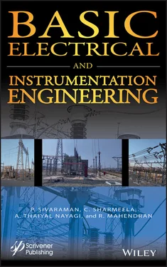
P. Sivaraman - Basic Electrical and Instrumentation Engineering

Здесь есть возможность читать онлайн «P. Sivaraman - Basic Electrical and Instrumentation Engineering» — ознакомительный отрывок электронной книги совершенно бесплатно, а после прочтения отрывка купить полную версию. В некоторых случаях можно слушать аудио, скачать через торрент в формате fb2 и присутствует краткое содержание. Жанр: unrecognised, на английском языке. Описание произведения, (предисловие) а так же отзывы посетителей доступны на портале библиотеки ЛибКат.

Basic Electrical and Instrumentation Engineering: краткое содержание, описание и аннотация

Предлагаем к чтению аннотацию, описание, краткое содержание или предисловие (зависит от того, что написал сам автор книги «Basic Electrical and Instrumentation Engineering»). Если вы не нашли необходимую информацию о книге — напишите в комментариях, мы постараемся отыскать её.

Electrical and instrumentation engineering is changing rapidly, and it is important for the veteran engineer in the field not only to have a valuable and reliable reference work which he or she can consult for basic concepts, but also to be up to date on any changes to basic equipment or processes that might have occurred in the field. Covering all of the basic concepts, from three-phase power supply and its various types of connection and conversion, to power equation and discussions of the protection of power system, to transformers, voltage regulation, and many other concepts, this volume is the one-stop, «go to» for all of the engineer's questions on basic electrical and instrumentation engineering.
There are chapters covering the construction and working principle of the DC machine, all varieties of motors, fundamental concepts and operating principles of measuring, and instrumentation, both from a «high end» point of view and the point of view of developing countries, emphasizing low-cost methods.
A valuable reference for engineers, scientists, chemists, and students, this volume is applicable to many different fields, across many different industries, at all levels. It is a must-have for any library.
Basic Electrical and Instrumentation Engineering — читать онлайн ознакомительный отрывок

Ниже представлен текст книги, разбитый по страницам. Система сохранения места последней прочитанной страницы, позволяет с удобством читать онлайн бесплатно книгу «Basic Electrical and Instrumentation Engineering», без необходимости каждый раз заново искать на чём Вы остановились. Поставьте закладку, и сможете в любой момент перейти на страницу, на которой закончили чтение.

Тёмная тема
Сбросить

Интервал:

Закладка:

Сделать

3 Chapter 3Figure 3.1 Construction of the DC machine.Figure 3.2 Armature of the DC machine.Figure 3.3 Typical lap winding.Figure 3.4 Typical simple lap winding.Figure 3.5 Duplex lap winding.Figure 3.6 Typical wave winding.Figure 3.7 Construction of rotor.Figure 3.8 Fleming right-hand rule.Figure 3.9 Relation between the motion and flux.Figure 3.10 Main flux by permanent magnet.Figure 3.11 Flux produced by current carrying conductor.Figure 3.12 Conductor flux is opposed to the main flux.Figure 3.13 Direction of force.Figure 3.14 Fleming left hand.Figure 3.15Figure 3.16 Circuit model.Figure 3.17 Representation of DC generator.Figure 3.18 Circuit diagram of separately excited DC generator.Figure 3.19 DC shunt generator.Figure 3.20 Circuit diagram of DC series generator.Figure 3.21 Long shunt DC compound generator.Figure 3.22 Short shunt compound generator.Figure 3.23 No load characteristics at constant speed.Figure 3.24 No load characteristics for different speed.Figure 3.25 Circuit diagram of separately excited DC generator.Figure 3.26 Open circuit characteristics of separately excited DC generator.Figure 3.27 Load characteristics of separately excited DC generator.Figure 3.28 Internal and external characteristics.Figure 3.29 Circuit diagram of DC shunt generator.Figure 3.30 Internal characteristics.Figure 3.31 External characteristics.Figure 3.32 Circuit diagram of DC series motor.Figure 3.33 Characteristics of I aor I Lor I seVS terminal voltage (V t).Figure 3.34 Full load current VS terminal voltage (V t).Figure 3.35 Winding connection of DC shunt motor.Figure 3.36 Winding connection of DC series motor.Figure 3.37 Long shunt DC compound motor.Figure 3.38 Short shunt compound motor.Figure 3.39 Torque vs. armature current characteristics of a DC shunt motor.Figure 3.40 Speed vs. armature current characteristics of a DC shunt motor.Figure 3.41 Speed vs. torque characteristics of a DC shunt motor.Figure 3.42 Torque vs. armature current characteristics of a DC series motor.Figure 3.43 Speed vs. armature current characteristics of a DC series motor.Figure 3.44 Speed vs. torque characteristics of a DC series motor.Figure 3.45 Torque vs. armature current characteristics of a DC compound motor.Figure 3.46 Speed vs. armature current characteristics of a DC compound motor.Figure 3.47 Speed vs. torque characteristics of a DC compound motor.Figure 3.48 Circuit diagram of three-point starter.Figure 3.49 Circuit diagram of four point starter.Figure 3.50 Circuit diagram of two-point starter.Figure 3.51 Circuit diagram for flux control-based DC shunt motor speed control.Figure 3.52 Speed vs. field current characteristics.Figure 3.53 Circuit diagram for armature voltage control-based DC shunt motor sp...Figure 3.54 Relationship of armature voltage and speed.Figure 3.55 Circuit diagram for applied voltage-based DC shunt motor speed contr...Figure 3.56 Circuit diagram for field diverter-based DC series motor speed contr...Figure 3.57 Characteristics of speed vs. armature current.Figure 3.58 Circuit diagram for armature diverter-based DC series motor speed co...Figure 3.59 Circuit diagram for tapped field-based DC series motor speed control...Figure 3.60 Circuit diagram for series connected field-based DC series motor spe...Figure 3.61 Circuit diagram for parallel connected field-based DC series motor s...Figure 3.62 Circuit diagram for rheostat-based DC series motor speed control.Figure 3.63 Relationship between speed vs. armature current.Figure 3.64 Circuit diagram of applied voltage-based speed control of DC series ...Figure 3.65 Construction of universal motor.

4 Chapter 4Figure 4.1 Construction of stator.Figure 4.2 Typical view of stator of an induction motor.Figure 4.3 Arrangement of squirrel cage rotor.Figure 4.4 Skewed arrangement of squirrel cage rotor.Figure 4.5 Typical skewed arrangement of squirrel cage induction motor.Figure 4.6 Slip ring rotor.Figure 4.7 Typical slip ring induction motor.Figure 4.8 Typical slip ring and carbon brush arrangement.Figure 4.9 Direction of current flow in rotor circuit.Figure 4.10 Direction of current flow in rotor circuit.Figure 4.11 The relation of the rotor, resistance and reactance.Figure 4.12 Torque–Slip characteristics of an induction motor.Figure 4.13 Primary and secondary winding of the three-phase induction motor.Figure 4.14 Circuit diagram of an induction motor as transformer.Figure 4.15 Equivalent circuit diagram of an induction motor.Figure 4.16 Equivalent circuit of a rotor.Figure 4.17 Equivalent circuit.Figure 4.18 Equivalent circuit.Figure 4.19 Construction of the single-phase induction motor.Figure 4.20 Construction of rotor.Figure 4.21 Split-phase induction motor.Figure 4.22 The phase difference (α) between two currents.Figure 4.23 Speed vs. full load torque.Figure 4.24 Circuit diagram of capacitor-start induction motor.Figure 4.25 Voltage and current characteristics.Figure 4.26 Circuit diagram of capacitor-start and capacitor-run induction motor...Figure 4.27 Speed vs. full load torque.Figure 4.28 Construction of shaded-pole motor.Figure 4.29 Speed vs. full load torque.Figure 4.30 Three-phase induction motor with DOL starter.Figure 4.31 Practical DOL starter (Courtesy: Larson and Toubro Limited).Figure 4.32 Circuit diagram of primary resistor or reactor.Figure 4.33 Autotransformer starter.Figure 4.34 Star-Delta starter.Figure 4.35 Slip ring induction motor.Figure 4.36 Speed control of induction motor using auto transformer.Figure 4.37 Speed control of induction motor using primary resistorFigure 4.38 Stator frequency control.Figure 4.39 Schematic diagram of V/F control.Figure 4.40 Typical V/F controller. Courtesy: ABBFigure 4.41 Cascaded type speed control for slip ring induction motor.Figure 4.42 Speed control of slip ring induction motor by external resistance.Figure 4.43 Construction of synchronous motor.Figure 4.44 Step angle of stepper motor.Figure 4.45 Construction of BLDC motor.Figure 4.46 Arrangement of armature winding in the slot.Figure 4.47 Salient pole type rotor.Figure 4.48 Smooth cylindrical type rotor.Figure 4.49 Magnetic field.Figure 4.50 Flux linkage.Figure 4.51 Relationship between the load current and terminal voltage.

5 Chapter 5Figure 5.1 Classification of instruments.Figure 5.2 Tangent Galvanometer (Courtesy: Tangent Galvonometer, Magnetic Field ...Figure 5.3 Relationship of B and B h.Figure 5.4 Rayleigh’s current balance.Figure 5.5 Analog signal.Figure 5.6 Digital signal.Figure 5.7 Controlling torque due to gravity.Figure 5.8 Spring control.Figure 5.9 Gravity control.Figure 5.10 Time vs. final deflection.Figure 5.11 Air friction damping.Figure 5.12 (a) Fluid friction damping. (b) Fluid friction damping.Figure 5.13 Eddy friction damping.Figure 5.14 D’Arsonval movement.Figure 5.15 DC ammeter.Figure 5.16 Multi-range DC ammeter.Figure 5.17 DC voltmeter.Figure 5.18 Multi-range voltmeter; (i) Parallel connection and (ii) Series conne...Figure 5.19 (a) Basic Ohmmeter Circuit Diagram.Figure 5.19 (b) Series type Ohmmeter. (c) Shunt type Ohmmeter.Figure 5.20 Electrodynamometer.Figure 5.21 Electrodynamometer ammeter circuit.Figure 5.22 Electrodynamometer in power measurement.Figure 5.23 Electrodynamometer Wattmeter.Figure 4.24 DC voltage measurement.Figure 5.25 AC voltage measurement.Figure 5.26 DC and AC voltage measurement.Figure 5.27 (a) and (b) Resistance measurement.Figure 5.28 Block diagram of cathode ray oscilloscope.Figure 5.29 Basic elements of storage mesh CRT.Figure 5.30 The charge pattern on a mesh storage.Figure 5.31 Phosphor storage oscilloscope.Figure 5.32 Images of CRO (Courtesy: Cathode Ray Oscilloscope, Product Type: Bio...Figure 5.33 Block diagram of digital storage oscilloscope.Figure 5.34 Waveform of digital storage oscilloscope.Figure 5.35 Digital storage oscilloscope (Courtesy: Digital Storage Oscilloscope...Figure 5.36 (a) and (b) Waveform of input vs. output.Figure 5.37 Galvonometer name plate (Courtesy: Galvanometer Analog Besto (311/31...Figure 5.38 Galvonometer (Courtesy: Galvanometer - Analog - BESTO (311/312 A)).Figure 5.39 Input vs. output of linearity.Figure 5.40 (a) Span drift. (b) Zero drift.Figure 5.41 Reproducibility.Figure 5.42 Image of stability measuring instruments (Courtesy: Stability Measur...Figure 5.43 Dynamic error.Figure 5.44 Flowchart of types of errors.Figure 5.45 Block diagram of measuring system.Figure 4.46 Block diagram of LVDT.Figure 5.47 Thermocouple.Figure 5.48 Strain gauge.Figure 5.49 Block diagram of transducer.Figure 5.50 Capacitive transducer.Figure 5.51 Parallel plate capacitance.Figure 5.52 Cylindrical capacitive transducer.Figure 5.53 Semicircular capacitive transducer.Figure 5.54 Dielectric placed between two plates.Figure 5.55 Inductive transducer.Figure 5.56 Self-inductance.Figure 5.57 Photoelectric transducer.Figure 5.58 Photoelectric transducer.Figure 5.59 Gas-filled phototube.Figure 5.60 Photo-multiplier tube.Figure 5.61 (a) Photo conductive cell. (b) Symbol.Figure 5.62 Photoconductive cell Illumination characteristics.Figure 5.63 Photovoltaic cell.Figure 5.64 P-N junction solar cell with resistive load.Figure 5.65 Quartz crystal.Figure 5.66 Diagram of piezoelectric transducer.Figure 5.67 Hall effect.Figure 5.68 Measurement of displacement.Figure 5.69 Measurement of current.

Читать дальше
Тёмная тема
Сбросить

Интервал:

Закладка:

Сделать

Похожие книги на «Basic Electrical and Instrumentation Engineering»

Представляем Вашему вниманию похожие книги на «Basic Electrical and Instrumentation Engineering» списком для выбора. Мы отобрали схожую по названию и смыслу литературу в надежде предоставить читателям больше вариантов отыскать новые, интересные, ещё непрочитанные произведения.


Отзывы о книге «Basic Electrical and Instrumentation Engineering»

Обсуждение, отзывы о книге «Basic Electrical and Instrumentation Engineering» и просто собственные мнения читателей. Оставьте ваши комментарии, напишите, что Вы думаете о произведении, его смысле или главных героях. Укажите что конкретно понравилось, а что нет, и почему Вы так считаете.

x