Peter M. Curtis - Maintaining Mission Critical Systems in a 24/7 Environment
Здесь есть возможность читать онлайн «Peter M. Curtis - Maintaining Mission Critical Systems in a 24/7 Environment» — ознакомительный отрывок электронной книги совершенно бесплатно, а после прочтения отрывка купить полную версию. В некоторых случаях можно слушать аудио, скачать через торрент в формате fb2 и присутствует краткое содержание. Жанр: unrecognised, на английском языке. Описание произведения, (предисловие) а так же отзывы посетителей доступны на портале библиотеки ЛибКат.
- Название:Maintaining Mission Critical Systems in a 24/7 Environment
- Автор:
- Жанр:
- Год:неизвестен
- ISBN:нет данных
- Рейтинг книги:5 / 5. Голосов: 1
-
Избранное:Добавить в избранное
- Отзывы:
-
Ваша оценка:
Maintaining Mission Critical Systems in a 24/7 Environment: краткое содержание, описание и аннотация
Предлагаем к чтению аннотацию, описание, краткое содержание или предисловие (зависит от того, что написал сам автор книги «Maintaining Mission Critical Systems in a 24/7 Environment»). Если вы не нашли необходимую информацию о книге — напишите в комментариях, мы постараемся отыскать её.
Features new and updated content throughout, including new chapters on energy security and on integrating cleaner and more efficient energy into mission critical applications Defines power quality terminology and explains the causes and effects of power disturbances Provides in-depth explanations of each component of mission critical systems, including standby generators, raised access floors, automatic transfer switches, uninterruptible power supplies, and data center cooling and fuel systems Contains in-depth discussion of the evolution and future of the mission critical facilities industry Includes PowerPoint presentations with voiceovers and a digital/video library of information relevant to the mission critical industry
in a 24/7 Environment is a must-read reference and training guide for architects, property managers, building engineers, IT professionals, data center personnel, electrical & mechanical technicians, students, and others involved with all types of mission critical equipment.
Maintaining Mission Critical Systems in a 24/7 Environment — читать онлайн ознакомительный отрывок
Ниже представлен текст книги, разбитый по страницам. Система сохранения места последней прочитанной страницы, позволяет с удобством читать онлайн бесплатно книгу «Maintaining Mission Critical Systems in a 24/7 Environment», без необходимости каждый раз заново искать на чём Вы остановились. Поставьте закладку, и сможете в любой момент перейти на страницу, на которой закончили чтение.
Интервал:
Закладка:
On‐site Generation – If the worst‐case short circuit levels are to be calculated, all generations that can operate in parallel with the Utility supply must be included in the model. Rated voltage, kVA, power factor, and generator subtransient and transient impedances should be obtained from the equipment nameplate or manufacturer for input into the model.
In‐Service Motors – Rotating electric motors have stored kinetic energy, and under fault conditions, a motor can act as a generator for a short period and return some of this stored energy into the fault in the form of short circuit current. All across the line, induction motors and synchronous motors should be modeled. If induction motors are supplied by Variable Frequency Drives, only motors that are fed from drives that are regenerative should be included. Typically lumping contributing motors together on each bus provides reasonably accurate results. Software packages have default impedances and power factors that cover typical motors. Actual impedances should be used where known, and especially for very large motors.
UPS Systems – UPS systems often are limited as to the amount of short circuit current they can contribute to a downstream fault. Consult with the equipment supplier for characteristics of any such equipment on the system being analyzed.
All impedances in the system must be defined and inputted:
Transformers – Correct modeling of transformers is critical to an accurate model. Winding voltage ratings, kVA ratings, and impedances should be obtained from transformer nameplates or manufacturers. Winding connections must be inputted, as well as any ground impedances.
Cables – Wire and cable size, length, and routing type must be included in the model. Where existing cables sizes are not known use the NEC as a reference and include any assumptions that you made in the report as a reference for future investigations. Cable lengths can be estimated based on a site visit and inspection, or by making reasonable assumptions from building and site plans. Whether cable is routed in steel conduit/raceway or not can also make a difference in cable impedance.
Reactors – Where line reactors are included to limit short circuit current or minimize harmonics, they shall be included in the model. Obtain ratings from the equipment nameplate or the manufacturer.
Once the electrical distribution system model is created, the system can be analyzed for all operating scenarios. These might include generators operating or not, bus tie breakers closed or open, etc. The maximum short circuit fault current calculated from any of the scenarios should be recorded at each bus in the distribution system. Protective device manufacturers assign short‐circuit interrupting and fault withstand ratings to their equipment, signifying the maximum fault condition under which the device may be safely applied. The currents calculated in an SCS are used to specify the required ratings for new equipment and to evaluate the adequacy of existing system components to withstand and interrupt these high magnitude currents. Once the electrical distribution system is modeled, proposed changes in system configuration can be analyzed in order to determine what, if any, equipment must be upgraded to support the proposed changes. An up to date SCS is also a requirement for Protective Device Coordination Studies as well as Arc‐Flash Hazard Analysis, which is an assessment, conducted by a safety expert, to evaluate the electrical equipment and power systems to predict the potential for or incident energy of an arc flash. More information on this topic is included in Chapter 4.
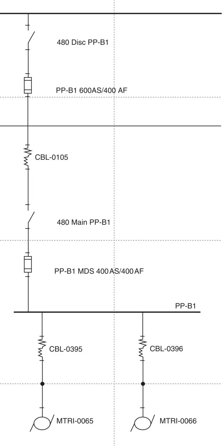
Figure 3.2Sample SCS Screenshot
(Courtesy of PMC Group One, LLC)
Coordination Study
The goal of a Protective Device Coordination Study is to determine overcurrent device settings and selections that maximize selectivity and power system reliability. In a well‐coordinated protective device, scheme faults are cleared by the nearest upstream protective device. This minimizes the portion of the electrical distribution system interrupted as a result of a fault or other disturbances. At the main distribution panel level, feeder breakers/fuses should trip before the main. Likewise, panel board branch breakers should trip before the feeder breaker/fuse supplying the panel.
As with Short Circuit Studies, a Protective Device Coordination is usually performed using the same specialized integrated software that is used for the Short Circuit, Load Flow, and Arc‐Flash calculations. Protective device types, ratings, and settings can be incorporated while the model is built or added after initial studies are completed. The use of computerized calculations allows the system protection engineer to evaluate a number of setting options in a short period of time, thereby allowing him (or her) to fine‐tune settings to achieve the best possible coordination.
Using the computer model, a Time Current Curve (TCC) is developed for each circuit fed from Service Switchboards and other critical buses. The curve includes the over current devices for the largest loads in series on the circuit – the worst case from a coordination aspect. All fuses, breakers, electromechanical or electronic relays, and trip devices are entered into the computer model, if not entered previously. Transformer and cable damage curves should be selected for inclusion on the TCC to verify that critical equipment is being protected. Transformer inrush points must be included to verify that the protective device feeding the unit will not operate when the transformer is energized. Device selection and settings from the database are reviewed to determine if changes are required to improve coordination. If so, settings or selection are modified, and the resulting TCC’s are printed for inclusion in the report. Protective device settings and selections are also summarized in tabular form.
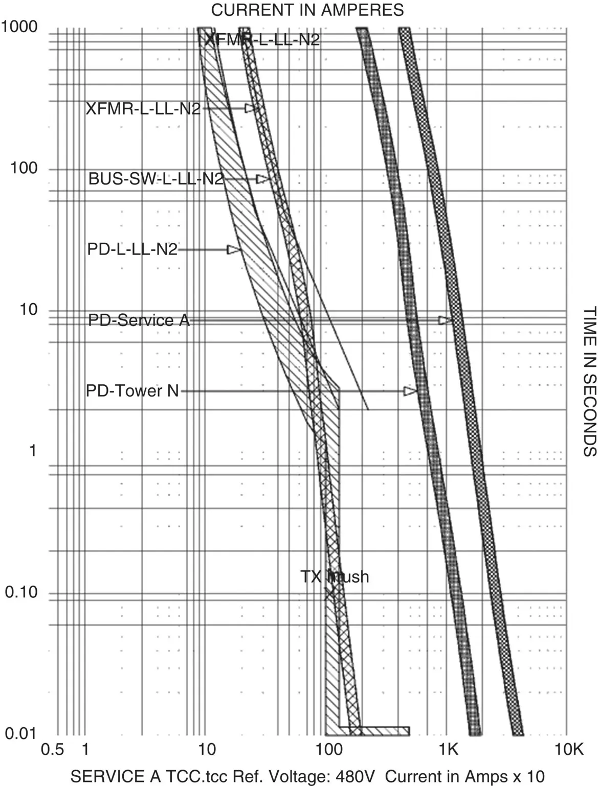
Figure 3.3Sample TCC Curve Analysis
( Source: Courtesy of PMC Group One, LLC)
In many cases, protective device coordination is a matter of compromise. Rather than being a choice of black or white, device coordination requires making selections that result in the best coordination that can be achieved with the devices that are installed: fuse characteristics are not as varied as electronic trip devices; instantaneous elements in series cannot be reliably coordinated; transformer protection must be selected to provide protection from damage from a fault while passing inrush current when the unit is energized.
Luckily, where power system reliability must be maximized, and therefore strict coordination is required, electronic relays and trip devices offer a variety of settings, curve shapes, and other functions that allow the system protection engineer to achieve this goal. Electronic relays come with a variety of trip characteristic curves, which, along with time delay and pick‐up settings, allow a great deal of flexibility when programming the device. The Zone Selective Interlocking feature available in many static trip devices allows the arming of Instantaneous settings on breakers in series without losing coordination. The upstream breaker trip device (such as the main device on a bus) communicates with downstream breakers. If the downstream device sees a fault current event, it sends a signal to the main device to block tripping the main breaker, thus allowing the downstream device to operate, minimizing the extent of the electrical system affected by the fault.
Читать дальшеИнтервал:
Закладка:
Похожие книги на «Maintaining Mission Critical Systems in a 24/7 Environment»
Представляем Вашему вниманию похожие книги на «Maintaining Mission Critical Systems in a 24/7 Environment» списком для выбора. Мы отобрали схожую по названию и смыслу литературу в надежде предоставить читателям больше вариантов отыскать новые, интересные, ещё непрочитанные произведения.


Обсуждение, отзывы о книге «Maintaining Mission Critical Systems in a 24/7 Environment» и просто собственные мнения читателей. Оставьте ваши комментарии, напишите, что Вы думаете о произведении, его смысле или главных героях. Укажите что конкретно понравилось, а что нет, и почему Вы так считаете.