Gerhard Ersdal - Underwater Inspection and Repair for Offshore Structures
Здесь есть возможность читать онлайн «Gerhard Ersdal - Underwater Inspection and Repair for Offshore Structures» — ознакомительный отрывок электронной книги совершенно бесплатно, а после прочтения отрывка купить полную версию. В некоторых случаях можно слушать аудио, скачать через торрент в формате fb2 и присутствует краткое содержание. Жанр: unrecognised, на английском языке. Описание произведения, (предисловие) а так же отзывы посетителей доступны на портале библиотеки ЛибКат.
- Название:Underwater Inspection and Repair for Offshore Structures
- Автор:
- Жанр:
- Год:неизвестен
- ISBN:нет данных
- Рейтинг книги:4 / 5. Голосов: 1
-
Избранное:Добавить в избранное
- Отзывы:
-
Ваша оценка:
Underwater Inspection and Repair for Offshore Structures: краткое содержание, описание и аннотация
Предлагаем к чтению аннотацию, описание, краткое содержание или предисловие (зависит от того, что написал сам автор книги «Underwater Inspection and Repair for Offshore Structures»). Если вы не нашли необходимую информацию о книге — напишите в комментариях, мы постараемся отыскать её.
is complementary to the authors’ book
, also from Wiley. This important book:
Covers current inspection and monitoring techniques to evaluate existing structures Includes coverage of robotic (ROV) inspection and repair methods Provides an overview of repair and maintenance techniques applicable to the splash-zone and underwater operations Written for engineers, designers and safety auditors working with offshore structures.
is a comprehensive resource for understanding how to effectively inspect and repair these vulnerable structures.
Underwater Inspection and Repair for Offshore Structures — читать онлайн ознакомительный отрывок
Ниже представлен текст книги, разбитый по страницам. Система сохранения места последней прочитанной страницы, позволяет с удобством читать онлайн бесплатно книгу «Underwater Inspection and Repair for Offshore Structures», без необходимости каждый раз заново искать на чём Вы остановились. Поставьте закладку, и сможете в любой момент перейти на страницу, на которой закончили чтение.
Интервал:
Закладка:
1.3.1 Fixed Steel Structures
Fixed steel structures (jackets) consist of a steel spaceframe piled to the seabed ( Figure 4b), supporting a deck with space for drilling rigs, production facilities and crew quarters. Fixed steel structures are also used as a substructure for wind turbines. Steel jackets are usually made of tubular steel members. A typical six‐legged steel platform is shown in Figure 4b. Historically, the piles were driven directly through the legs and into the seabed. In more recent platforms the piles are typically connected to the legs by pile sleeves where the annulus between the sleeve and the pile is grouted. In a few cases, a specialized suction pile (bucket foundation) has been used, for example the Norwegian platforms Draupner 16/11‐E and Sleipner T. In addition to the basic structure there are frames for the conductors, j‐tubes, risers and caissons needed for production and operation. J‐tubes are typically used to enable small diameter flowlines, electrical cables or pipeline bundles to be connected to the topside facilities. Steel structures are subject to ageing processes such as fatigue and corrosion and hence life extension is a key issue with regard to the structure itself.
Jack‐ups ( Figure 4a) are self‐elevating units with a buoyant hull and several legs which when on location can be lowered to the seabed and raise the deck above the level of the sea thus creating a more stable facility for drilling and/or production. During operation in an elevated situation, jack‐ups behave like a fixed platform. Jack‐up rigs have been primarily used for exploratory drilling, but there are a few instances where they have also been used for production.
Monopiles ( Figure 5c) support the deck on a single pile / tower. These types of structures are particularly used for offshore wind energy production.
1.3.2 Floating Structures
Semi‐submersible units ( Figure 4d) have hulls, together with columns and pontoons, with sufficient buoyancy to enable the structure to float. Semi‐submersible platforms change draft by means of ballasting and de‐ballasting (changing the water level in seawater tanks). They are normally anchored to the seabed by mooring systems, usually a combination of chain and wire rope. However, semi‐submersibles can also be kept on station by dynamic positioning (DP), commonly used for semi‐submersibles as drilling units and flotels in deep water. The hull supports a deck on which various facilities for drilling and production can be installed. Semi‐submersible platforms are also being used for wind energy production, such as on the Kincardine wind farm in Scotland.
A tension leg platform (TLP) is of similar form to the semi‐submersible platform but is vertically moored by tension legs, which decrease the vertical motion significantly. A TLP is designed with excess buoyancy to ensure that the tension in the legs remains in all operational conditions.
A spar platform consists of a single moored large‐diameter vertical cylinder that is supporting the topside or a wind turbine. The cylinder is ballasted in the bottom (often by solid and heavy material) to provide stability. Spar‐type of structures are increasingly being used for floating wind energy production.
A ship‐shaped structure is a floating vessel similar in shape to a conventional ship, primarily used by the production and processing of hydrocarbons. These are often called a floating storage unit (FSU), a floating storage and offloading unit (FSO) or a floating production, storage and offloading unit (FPSO). The steel hull typically consists of plates in a main deck, side shells, turn‐of‐bilge and a bottom shell in addtion to tank tops and longitudinal bulkheads (wing tank bulkhead and centreline bulkhead) and transverse bulkheads. These main platings together form the ship beam. In most cases these plates are stiffened by girders and stiffeners. The plates are exposed to the loading from hydrostatic and dynamic pressure, which is transferred to the stiffeners and girder beams and into the structure. Ship‐shaped structures are usually moored to the seabed by chains or wire ropes, although they can also be held on station using a dynamic positioning system. These mooring systems will require underwater inspection and possibly repair.
Most of the details of floating structures can be inspected from the inside in near dry conditions and are, as such, not a part of this book. However, underwater inspection and repair of the mooring, anchors, outer skin, valves and attatchments are relevant and hence included in the book.
1.3.3 Concrete Platforms
Concrete is used in several different types of offshore structures, which include:
gravity‐based structures, or GBS (for example, the Norwegian platforms Statfjord A‐C and UK platform Brent C);
tension leg platforms, or TLP (the Norwegian platform Heidrun);spar platforms, particularly for wind energy production,
semi‐submersible platforms (the Norwegian platform Troll B);
Jarlan walls enclosing concrete tanks (the UK platform Ninian and the Norwegian platform Ekofisk Tank);
steel‐concrete hybrid (the UK platform Ravenspurn); and
articulated tower (used as a loading column on Maureen).
The first concrete structure to be installed in the Norwegian sector was the Ekofisk tank in 1973 and the first to be installed on the UKCS was Beryl Alpha in 1975. At the time of writing, there are 22 concrete gravity‐based platforms, together with one concrete tension leg platform (Heidrun), one concrete semi‐submersible platform (Troll B) and one concrete base for a steel upper section (Harding).
Due to the dominance of GBS‐type structures, this book will mainly focus on these, but some aspects will apply for all types of concrete structures. The main parts of a concrete gravity‐based structure (GBS) are:
legs, towers and shafts;
storage cells (caissons);
steel‐to‐concrete transition;
shaft‐to‐base junction;
prestressing anchorages;
splash zone;
foundations; and
cathodic protection system.
Most concrete structures rest on the seabed on a large caisson often with skirts that penetrate the seabed protecting the structure against horizontal and overturning forces ( Figure 4c). The size of the caisson and skirts depends on local soil conditions. The topside steel structure is usually supported on up to four concrete columns/shafts extending from the caisson through the sea surface. The caisson can be divided into cells, which may be used as compartments for oil storage or as ballast. One or two of the columns are usually drill shafts supporting conductor frames and well‐conductors. Some of the shafts, which may be water filled or dry, are normally outfitted mechanically.
1.4 Overview of this Book
In this book the important issues discussed so far are addressed by the following topics as indicated in Figure 6:
regulatory requirements for inspection and repair (Chapter 2);
where and when a structural inspection is needed (Chapter 6);
what tools and methods can be used to inspect structures and how inspection tools are deployed (Chapter 4);
types of damage that are found on offshore structures (Chapter 3);
what tools and methods can be used to monitor structures (Chapter 5);
how is the information maintained about the design, fabrication and installation in addition to the history of operation and inspection results (Chapter 6.1.5);
when is an anomaly in a structure acceptable and when is mitigation or repair needed (Chapter 7); and
which repair schemes are appropriate and what is the strength and fatigue life of a repaired component (Chapter 8).
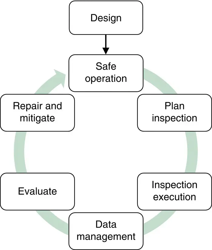
Figure 6 The management process for safe operation by inspection and mitigation.
Читать дальшеИнтервал:
Закладка:
Похожие книги на «Underwater Inspection and Repair for Offshore Structures»
Представляем Вашему вниманию похожие книги на «Underwater Inspection and Repair for Offshore Structures» списком для выбора. Мы отобрали схожую по названию и смыслу литературу в надежде предоставить читателям больше вариантов отыскать новые, интересные, ещё непрочитанные произведения.


Обсуждение, отзывы о книге «Underwater Inspection and Repair for Offshore Structures» и просто собственные мнения читателей. Оставьте ваши комментарии, напишите, что Вы думаете о произведении, его смысле или главных героях. Укажите что конкретно понравилось, а что нет, и почему Вы так считаете.