Gerhard Ersdal - Underwater Inspection and Repair for Offshore Structures
Здесь есть возможность читать онлайн «Gerhard Ersdal - Underwater Inspection and Repair for Offshore Structures» — ознакомительный отрывок электронной книги совершенно бесплатно, а после прочтения отрывка купить полную версию. В некоторых случаях можно слушать аудио, скачать через торрент в формате fb2 и присутствует краткое содержание. Жанр: unrecognised, на английском языке. Описание произведения, (предисловие) а так же отзывы посетителей доступны на портале библиотеки ЛибКат.
- Название:Underwater Inspection and Repair for Offshore Structures
- Автор:
- Жанр:
- Год:неизвестен
- ISBN:нет данных
- Рейтинг книги:4 / 5. Голосов: 1
-
Избранное:Добавить в избранное
- Отзывы:
-
Ваша оценка:
Underwater Inspection and Repair for Offshore Structures: краткое содержание, описание и аннотация
Предлагаем к чтению аннотацию, описание, краткое содержание или предисловие (зависит от того, что написал сам автор книги «Underwater Inspection and Repair for Offshore Structures»). Если вы не нашли необходимую информацию о книге — напишите в комментариях, мы постараемся отыскать её.
is complementary to the authors’ book
, also from Wiley. This important book:
Covers current inspection and monitoring techniques to evaluate existing structures Includes coverage of robotic (ROV) inspection and repair methods Provides an overview of repair and maintenance techniques applicable to the splash-zone and underwater operations Written for engineers, designers and safety auditors working with offshore structures.
is a comprehensive resource for understanding how to effectively inspect and repair these vulnerable structures.
Underwater Inspection and Repair for Offshore Structures — читать онлайн ознакомительный отрывок
Ниже представлен текст книги, разбитый по страницам. Система сохранения места последней прочитанной страницы, позволяет с удобством читать онлайн бесплатно книгу «Underwater Inspection and Repair for Offshore Structures», без необходимости каждый раз заново искать на чём Вы остановились. Поставьте закладку, и сможете в любой момент перейти на страницу, на которой закончили чтение.
Интервал:
Закладка:
Offshore structures in the Gulf of Mexico have also failed during hurricanes. For example, Hurricane Andrew in 1992 caused significant damage to twenty‐two of the offshore regions, with older structures sustaining significant damage. Inspection was needed to determine the extent of the damage and in many cases this information led to the need for repair in order to resume operation. Several examples of hurricane damage in the GoM are reviewed later in this book.
Other offshore accidents have also occurred. Not all of these failures were a result of an anomaly that could be identified by inspection. Some were the results of under‐design, underprediction of loading, accidental damage and gross errors. Such failures typically initiate significant subsequent research work providing a better understanding of the cause of failure and appropriate inspection requirements. An example of such is the intensive work that was initiated on fatigue and crack inspection after the Alexander L. Kielland accident.
The reasons for inspection and repair can change over the life of a structure. Ersdal et al. (2019) review the statistics of failure for older offshore structures and show that these structures have a significant failure rate, particularly for floating structures. Figure 2shows the types of damage to critical hull members; this includes cracking of the hull, corrosion, vibration and other types. This figure also shows the trend for increasing damage with age. This is to be expected knowing that these structures will degrade and accumulate damage, which requires regular inspection and often subsequent repair and mitigation.
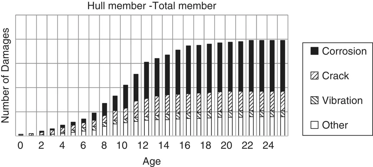
Figure 2 Damage to hull structural members by different causes and ship age for all ship types. Sources: Based on SSC (1992) “Marine Structural Integrity Programs (MSIP)”, Ship Structure Committee report no 365, 1992; SSC (2000). SSC‐416 Risk‐Based Life Cycle Management of Ship Structures, Ship Structure Committee report no 416, 2000.
As shown in Figure 2, damage rate increases with age, which is also indicated in a traditional bathtub curve as shown in Figure 3. In addition, structures are also known to experience some so‐called burn in failures at an early age. These two increases in failure rate are often reflected in a typical bathtub curve as shown in Figure 3. The phases in the life of a structure related to the bathtub curve can be described as:
an initial phase where anomalies arise from the design, fabrication and installation;
the maturity phase representing the useful operating life; and
the ageing and terminal phases representing the first and second part of the end of life.
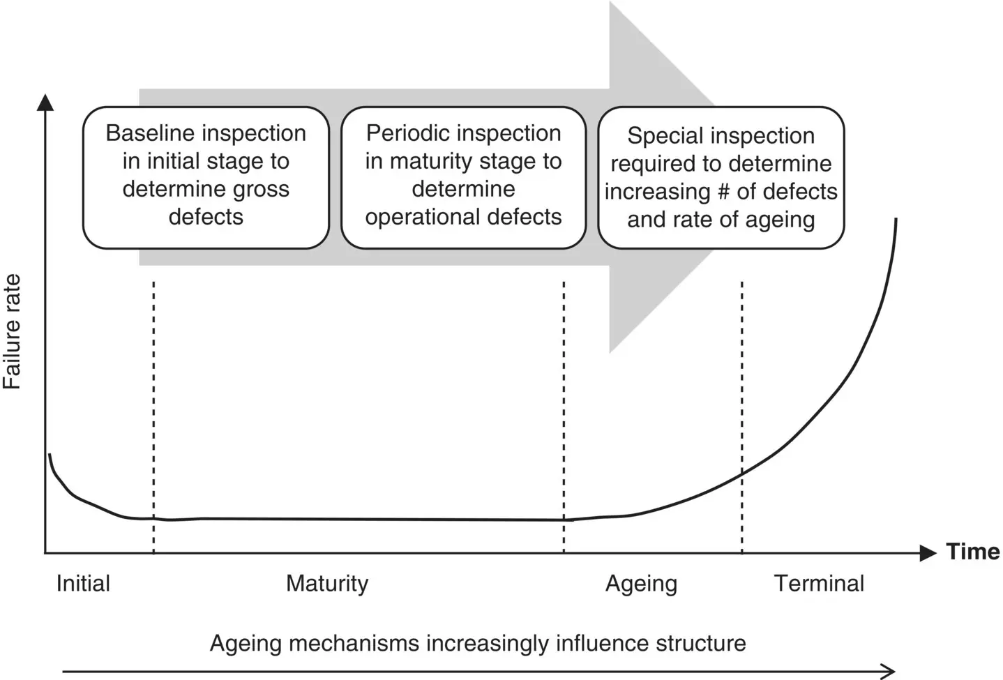
Figure 3 Typical bathtub curve. It should be noted that ageing may set in earlier if the structure is not managed properly.
Source: Based on HSE (2006). Plant ageing—Management of equipment containing hazardous fluids or pressure, HSE RR 509.
It is important to recognise that frequency, purpose and method of inspection depend on the phase in the bathtub curve (HSE 2006). In the initial phase, anomalies arising from gross errors in the design, fabrication and installation should be detected by early inspections (baseline inspection). The purpose of these early inspections is to determine the existence of gross errors and to provide confidence about the state of the structure. Any anomalies detected are expected to be rectified and the structure should at the end of this period “enter” the maturity phase.
In the maturity phase a lower failure rate is expected and the purpose of the inspection is to confirm that changes to the structure’s condition, configuration and loading are in line with expectation.
In addition, identification of unexpected and unforeseen anomalies and damage is needed, such as unexpected early fatigue cracks and corrosion damage and unforeseen accidental damage and load changes. Inspection in the maturity phase will often be periodic and can be calendar‐based, condition‐based or risk‐based. These strategies for inspection are discussed further in later chapters.
In the ageing and terminal phases the failure rate is expected to increase, although this is seldom recognised by structural integrity engineers. The purpose of inspection in these phases is to provide the basis for evaluation and the need for and prioritisation of repairs to ensure that the structure is still fit for purpose. Standards in some cases also require special inspections to be performed in these phases. The frequency of inspection is expected to increase compared to that in the maturity phase and even more so in the terminal phase.
1.3 Types of Offshore Structures
Inspection and repair depend on the type of structure and the material used. The types of platforms primarily used in the offshore industry are fixed with some variation and floating platforms. Examples of offshore structures are shown in Figure 4and Figure 5.
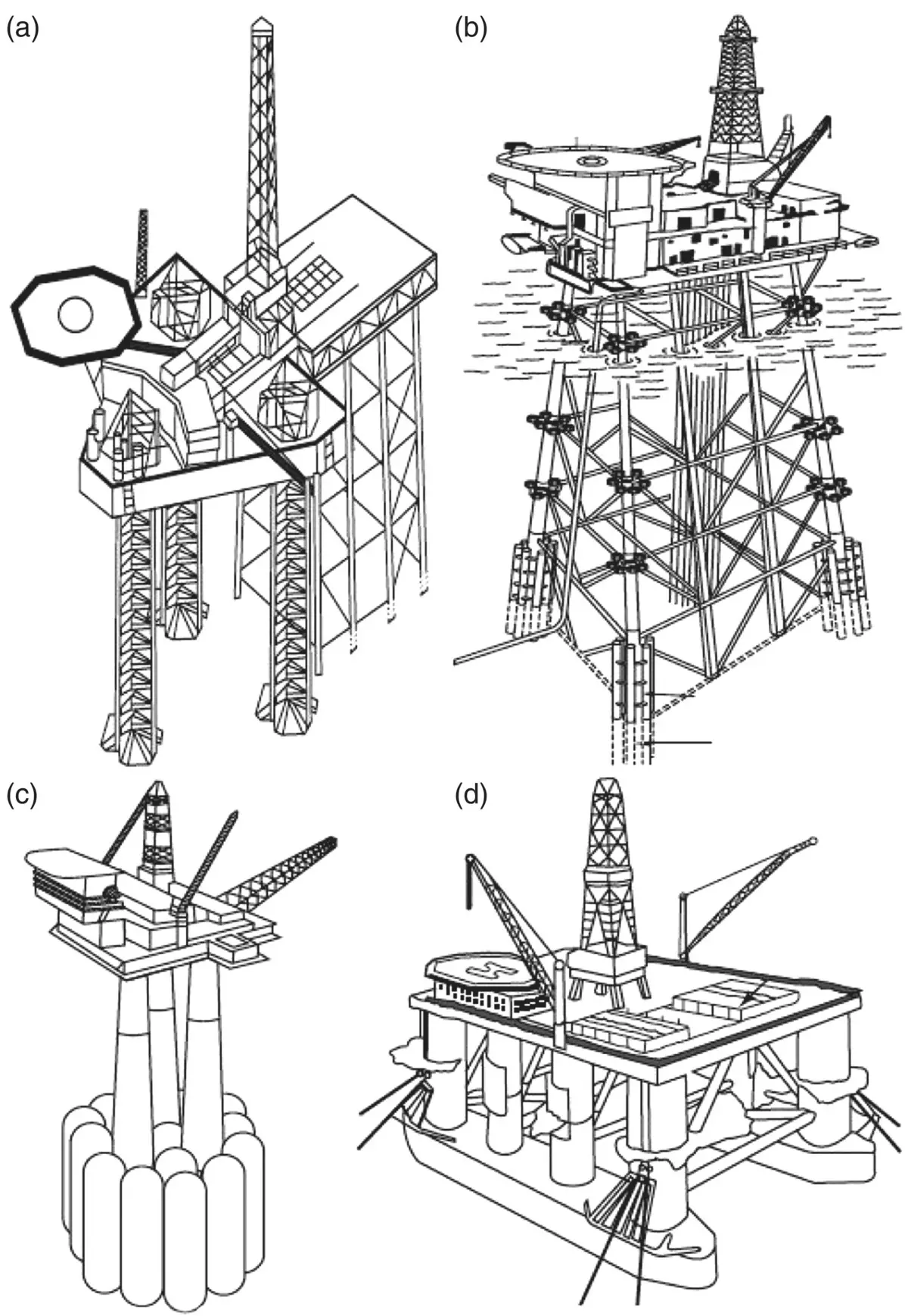
Figure 4 Examples of types of offshore structures: (a) is a jack‐up placed alongside a jacket structure, (b) is a jacket structure, (c) is a concrete gravity‐based structure and (d) is a semi‐submersible unit.
Source: Sundar, V. (2015), Ocean Wave Mechanics: Application in Marine Structures, © 2015, John Wiley & Sons.
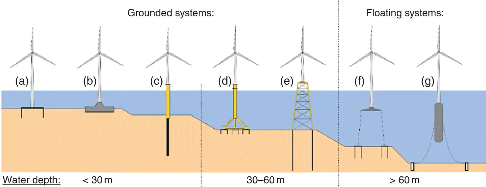
Figure 5 Various forms of wind turbine substructures: (a) suction pile caisson, (b) gravity‐based concrete foundation, (c) monopile, (d) tripod, (e) fixed steel structure (jacket), (f) tension leg platform, (g) spar buoy.
Source: Bhattacharya, S. (2019), Design of Foundations for Offshore Wind Turbines © 2019, John Wiley & Sons.
Fixed platforms typically are of the type:
fixed steel structures (jacket structures), which are mostly pile supported or suction anchor supported;
concrete gravity‐based structures;
jack‐ups; or
monopile.
Floating platforms are in general dependent on their watertight integrity and station keeping in addition to their structural integrity to function. The most used types of floating structures in the offshore industry include:
semi‐submersible platforms (mostly in steel, but one in concrete exists);
tension leg platforms (mostly in steel, but one in concrete exists);
ship‐shaped platforms and barge‐shaped platforms (mostly in steel, but a few in concrete have been made); and
spar platforms.
Structures must adhere to regional regulations (stationary structures) or to flag state regulations in combination with class society rules (mobile units). So‐called mobile offshore units (MOUs) are typically at a location for a limited time and inspection and repair are often performed at a yard at regular intervals. These yard periods allow for inspection and repair to be performed in controlled circumstances, often in dry conditions or benign conditions. In comparison, inspection and repair of stationary structures requires inspection and repair to be performed in an offshore environment and often underwater by an ROV. Hence, inspection and repair are rather different for these two types of structures, both with regards to the regulatory regime and the environment in which the inspection and repair is performed.
Читать дальшеИнтервал:
Закладка:
Похожие книги на «Underwater Inspection and Repair for Offshore Structures»
Представляем Вашему вниманию похожие книги на «Underwater Inspection and Repair for Offshore Structures» списком для выбора. Мы отобрали схожую по названию и смыслу литературу в надежде предоставить читателям больше вариантов отыскать новые, интересные, ещё непрочитанные произведения.


Обсуждение, отзывы о книге «Underwater Inspection and Repair for Offshore Structures» и просто собственные мнения читателей. Оставьте ваши комментарии, напишите, что Вы думаете о произведении, его смысле или главных героях. Укажите что конкретно понравилось, а что нет, и почему Вы так считаете.