Multifunctional Antennas and Arrays for Wireless Communication Systems
Здесь есть возможность читать онлайн «Multifunctional Antennas and Arrays for Wireless Communication Systems» — ознакомительный отрывок электронной книги совершенно бесплатно, а после прочтения отрывка купить полную версию. В некоторых случаях можно слушать аудио, скачать через торрент в формате fb2 и присутствует краткое содержание. Жанр: unrecognised, на английском языке. Описание произведения, (предисловие) а так же отзывы посетителей доступны на портале библиотеки ЛибКат.
- Название:Multifunctional Antennas and Arrays for Wireless Communication Systems
- Автор:
- Жанр:
- Год:неизвестен
- ISBN:нет данных
- Рейтинг книги:5 / 5. Голосов: 1
-
Избранное:Добавить в избранное
- Отзывы:
-
Ваша оценка:
Multifunctional Antennas and Arrays for Wireless Communication Systems: краткое содержание, описание и аннотация
Предлагаем к чтению аннотацию, описание, краткое содержание или предисловие (зависит от того, что написал сам автор книги «Multifunctional Antennas and Arrays for Wireless Communication Systems»). Если вы не нашли необходимую информацию о книге — напишите в комментариях, мы постараемся отыскать её.
will also earn a place in the libraries of engineers in related fields, like RF devices, who seek a one-stop reference for this essential technology.
Multifunctional Antennas and Arrays for Wireless Communication Systems — читать онлайн ознакомительный отрывок
Ниже представлен текст книги, разбитый по страницам. Система сохранения места последней прочитанной страницы, позволяет с удобством читать онлайн бесплатно книгу «Multifunctional Antennas and Arrays for Wireless Communication Systems», без необходимости каждый раз заново искать на чём Вы остановились. Поставьте закладку, и сможете в любой момент перейти на страницу, на которой закончили чтение.
Интервал:
Закладка:
Table 1.1 PIN diode states for reconfiguring the lower frequency bands while the higher band is consistently maintained.
| Switch table list | |||||
|---|---|---|---|---|---|
| LTE 17 (0.704–0.746 GHz) | LTE 13 (0.746–0.787 GHz) | LTE 14 (0.758–0.798 GHz) | GSM 850 (0.824–0.894 GHz) | EGSM (0.880–0.960 GHz) | |
| First switch | ON | ON | ON | ON | OFF |
| Second switch | ON | ON | ON | OFF | OFF |
| Third switch | ON | ON | OFF | OFF | OFF |
| Fourth switch | ON | OFF | OFF | OFF | OFF |
Current distribution ( Figure 1.6) shows current flow and hotspot for radiating element at the lower frequency end (780 MHz, Figure 1.6a) and the upper frequency end (1880 MHz, Figure 1.6b) for the proposed reconfigurable PIFA. Low and high bands have individual hotspots which can tune each band separately. Different sections of the radiator employ mutual coupling to obtain better matching and bandwidth.
Simulated and measured reflection coefficient magnitudes for the lower reconfigurable bands are compared in Figure 1.7a. It can be observed that the antenna is matched well below −7 dB between 704 and 960 MHz which includes the reconfigurable states of LTE 17, 13, 14, GSM, and EGSM. Similarly, Figure 1.7b shows the simulated and measured matching for the high‐frequency band. Once again, it can be observed that the antenna consistently maintains the matching level between 1710 and 2690 MHz better than −7 dB for all the switch states.
The 3D radiation patterns and total antenna efficiency were measured using the Satimo chamber. The total efficiency for the reconfigurable stages at the lower frequency bands and the consistent higher band is shown in Figure 1.8a and b, respectively. This efficiency takes care of all the possible losses in the antenna such as mismatch loss, Ohmic and dielectric losses, and losses due to the PIN diodes and bias components. The antenna efficiency is above 50% for all the switching states in the lower band and the higher band. The simulated and measured efficiencies agree reasonably well except toward edges of the bands.
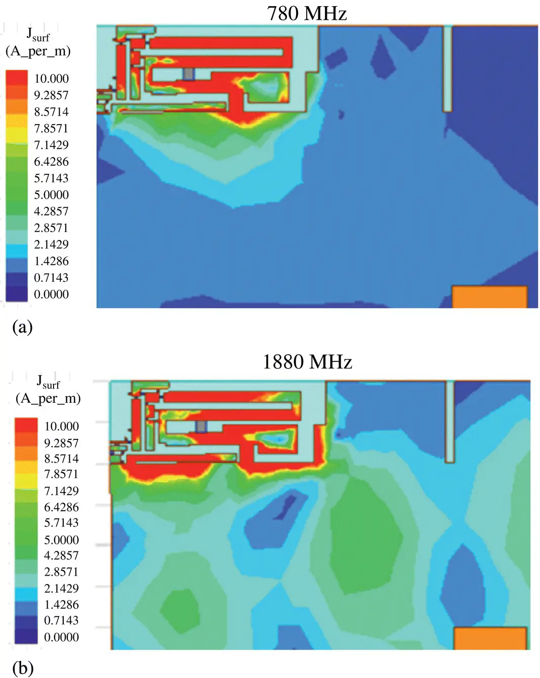
Figure 1.6 Surface current distribution for (a) 780 MHz in lower frequency band and (b) 1880 MHz in upper frequency band.
The simulated ( Figure 1.9a, c, e, g) and measured ( Figure 1.9b, d, f, h) 3D radiation pattern for the lower reconfigurable bands for the selected 720, 770, 850, and 910 MHz is shown in Figure 1.9. Similarly, simulated ( Figure 1.10a, c, e, g) and measured ( Figure 1.10b, d, f, h) 3D radiation pattern for the higher consistent bands for the selected 1710, 1880, 2100, and 2600 MHz is shown in Figure 1.10. From these figures, it can be observed that the patterns are near omnidirectional except toward the higher frequency end, where patterns show slight multilobes and nulls. In all the cases, realized peak gain is positive and around 2 dBi for both simulated and measured cases. Further, the patterns toward the higher end show some directionality due to the ground plane effect which tends to push the radiated energy in a direction causing diversity that is helpful when the MIMO antenna system is implemented.
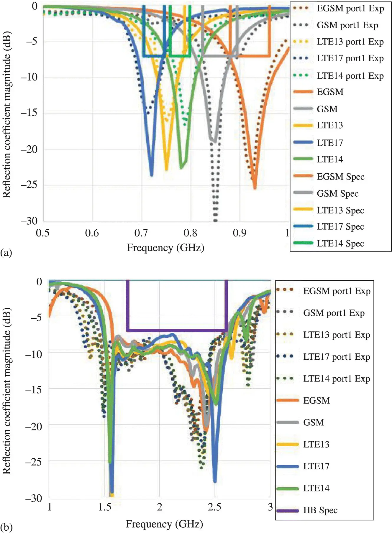
Figure 1.7 Comparison of the simulated (solid lines) and measured (dash lines) reflection coefficient magnitudes against specifications of the (a) lower 4G LTE frequency reconfigurable bands and (b) consistent higher frequency bands.
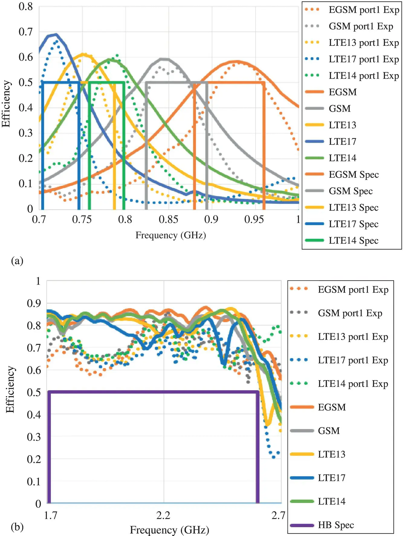
Figure 1.8 The simulated (solid lines) and measured (dash lines) total antenna efficiencies for (a) the reconfigurable states of the lower 4G bands and (b) the consistent higher frequency band.
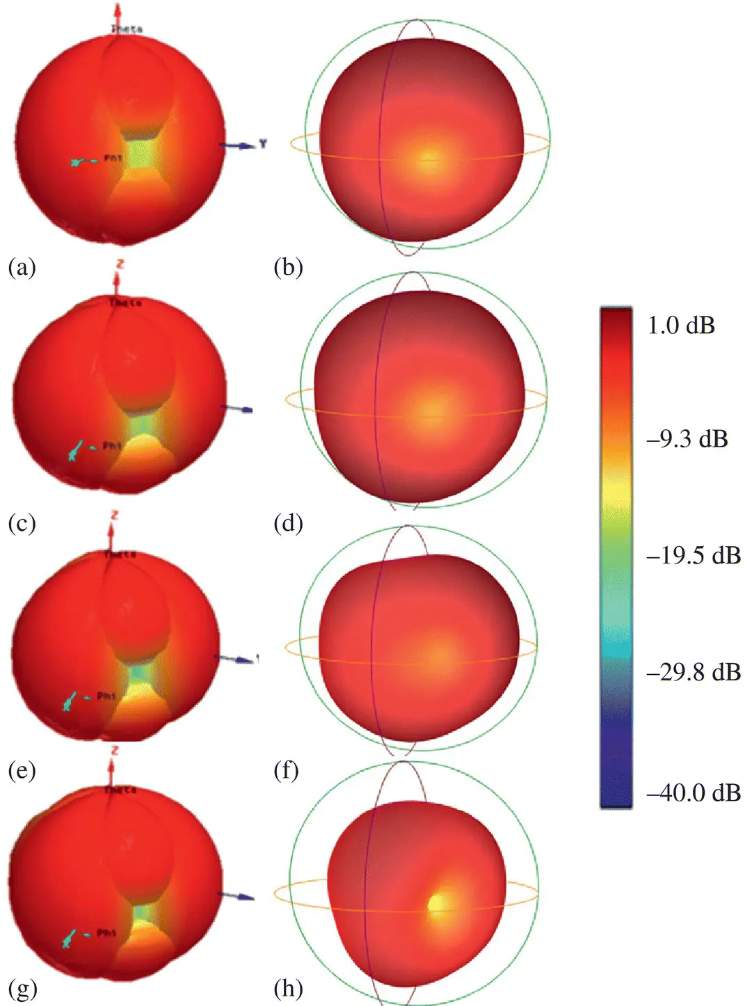
Figure 1.9 Simulated (a, c, e, g) and measured (b, d, f, h) near‐omnidirectional 3D radiation pattern at (a, b) 720 MHz, (c, d) 770 MHz, (e, f) 850 MHz, and (g, h) 910 MHz.
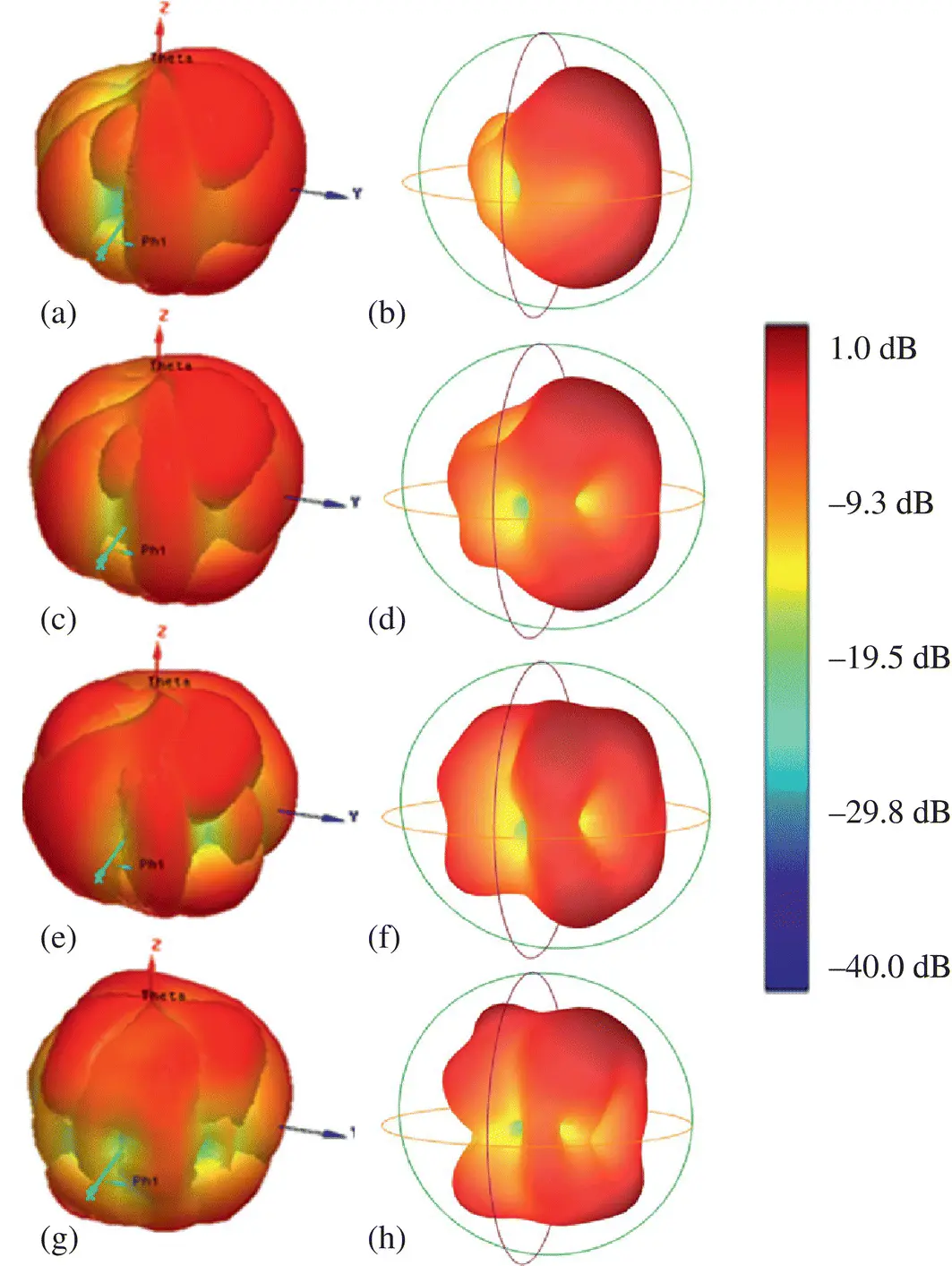
Figure 1.10 Simulated (a, c, e, g) and measured (b, d, f, h) near‐omnidirectional 3D radiation pattern at (a, b) 1710 MHz, (c, d) 1880 MHz, (e, f) 2100 MHz, and (g, h) 2600 MHz.
1.7 Frequency Agile/Tunable Antenna
A frequency agile or tunable antenna can be realized by integrating tunable RF components such as varactor diodes or RF micro‐electro‐mechanical‐systems (MEMS) variable capacitors in an antenna structure. Like a reconfigurable antenna, such antennas also require necessary bias networks such as those implemented in [2] and shown in Figure 1.4a–c and hence is not repeated again. The antenna impedance and radiation mechanism depends on the variation in effective permittivity which in turn is related to the change in capacitance variation. Frequency (f) of an antenna can be described as follows:
(1.1) 
where L and C are the inductance and capacitance of an antenna.
To demonstrate mechanism of such an antenna, an example is now discussed from [5]. The antenna utilizes a meandered planar portion on the right‐hand side, which includes a varactor diode and its biasing network and a rectangular‐shaped cutout portion on the left‐hand side on the central feed arm ( Figure 1.11). The varactor capacitance variation alters the electrical length of the meandered portion of the antenna, which in turn varies the resonance frequency of the antenna. In addition to the tunable meandered portion of the antenna, the design also includes a rectangular‐shaped cutout geometry for realizing higher band. Thus, this antenna follows a two‐step design approach.
In the first design step, the meandered line was chosen as the location for placement of the varactor diode. Since the meandered line enables the antenna to resonate at the lower frequency band, adding a varactor to this section allows the antenna to become tunable. To provide a wider tunable band between 690 and 970 MHz, the meandered line's electrical length is essentially increased by adding the varactor diode (SMV1281). After optimizing the antenna with the varactor diode set in place, Figure 1.12shows the meandered line length as M L= 137.5 mm, which is slightly below λ/2 at 970 MHz and the width of the meandered line is M W= 1.2 mm.
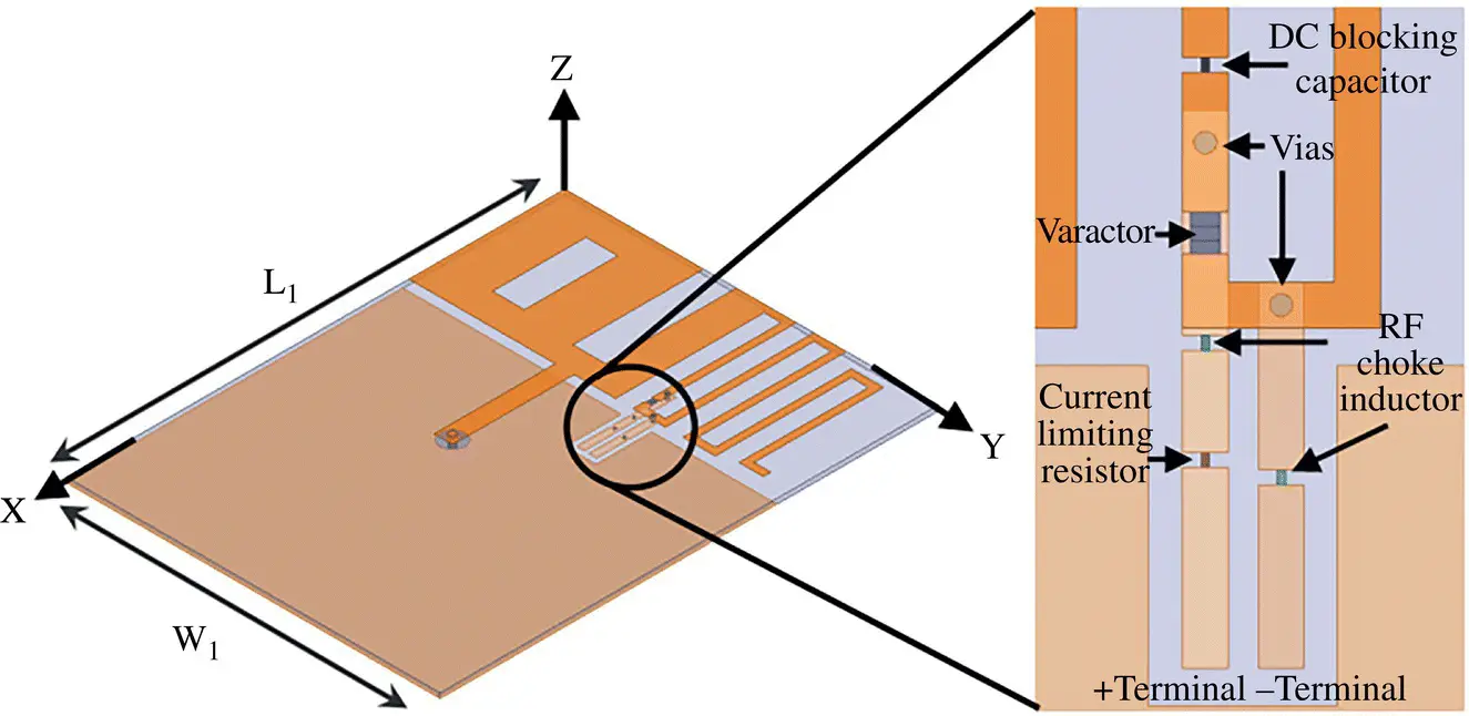
Figure 1.11 Antenna geometry with varactor diode and biasing network.
Source : Damman et al. [5].
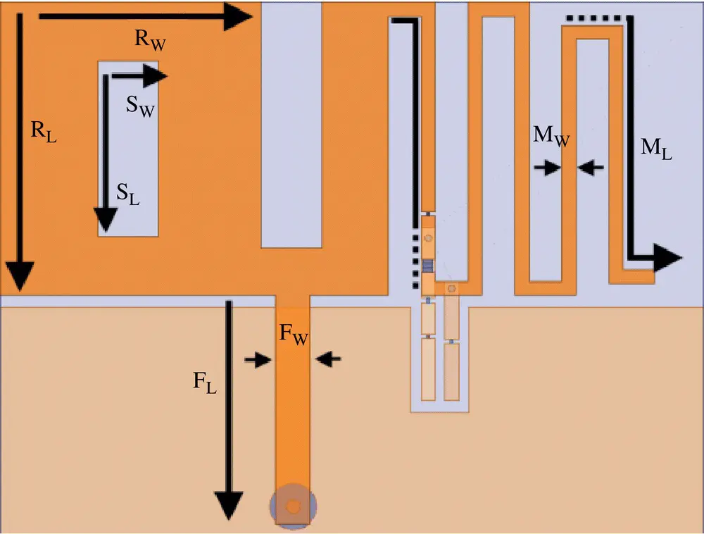
Figure 1.12 Design parameters for the low (right) and high bands (left).
Читать дальшеИнтервал:
Закладка:
Похожие книги на «Multifunctional Antennas and Arrays for Wireless Communication Systems»
Представляем Вашему вниманию похожие книги на «Multifunctional Antennas and Arrays for Wireless Communication Systems» списком для выбора. Мы отобрали схожую по названию и смыслу литературу в надежде предоставить читателям больше вариантов отыскать новые, интересные, ещё непрочитанные произведения.


Обсуждение, отзывы о книге «Multifunctional Antennas and Arrays for Wireless Communication Systems» и просто собственные мнения читателей. Оставьте ваши комментарии, напишите, что Вы думаете о произведении, его смысле или главных героях. Укажите что конкретно понравилось, а что нет, и почему Вы так считаете.