Rajib Taid - Mobile Communications Systems Development
Здесь есть возможность читать онлайн «Rajib Taid - Mobile Communications Systems Development» — ознакомительный отрывок электронной книги совершенно бесплатно, а после прочтения отрывка купить полную версию. В некоторых случаях можно слушать аудио, скачать через торрент в формате fb2 и присутствует краткое содержание. Жанр: unrecognised, на английском языке. Описание произведения, (предисловие) а так же отзывы посетителей доступны на портале библиотеки ЛибКат.
- Название:Mobile Communications Systems Development
- Автор:
- Жанр:
- Год:неизвестен
- ISBN:нет данных
- Рейтинг книги:5 / 5. Голосов: 1
-
Избранное:Добавить в избранное
- Отзывы:
-
Ваша оценка:
Mobile Communications Systems Development: краткое содержание, описание и аннотация
Предлагаем к чтению аннотацию, описание, краткое содержание или предисловие (зависит от того, что написал сам автор книги «Mobile Communications Systems Development»). Если вы не нашли необходимую информацию о книге — напишите в комментариях, мы постараемся отыскать её.
Mobile Communications Systems Development: A Practical Approach for System Understanding, Implementation and Deployment In-depth chapters cover the entire protocol stack from the Physical (PHY) to the Application layer, discuss theoretical and practical considerations, and describe software implementation based on the 3GPP standardized technical specifications. The book includes figures, tables, and sample computer code to help readers thoroughly comprehend the functions and underlying concepts of a mobile communications network. Each chapter includes an introduction to the topic and a chapter summary. A full list of references, and a set of exercises are also provided at the end of the book to test comprehension and strengthen understanding of the material. Written by a respected professional with more than 20 years’ experience in the field, this highly practical guide:
Provides detailed introductory information on GSM, GPRS, UMTS, and LTE mobile communications systems and networks Describes the various aspects and areas of the LTE system air interface and its protocol layers Covers troubleshooting and resolution of mobile communications systems and networks issues Discusses the software and hardware platforms used for the development of mobile communications systems network elements Includes 5G use cases, enablers, and architectures that cover the 5G NR (New Radio) and 5G Core Network
is perfect for graduate and postdoctoral students studying mobile communications and telecom design, electronic engineering undergraduate students in their final year, research and development engineers, and network operation and maintenance personnel.
Mobile Communications Systems Development — читать онлайн ознакомительный отрывок
Ниже представлен текст книги, разбитый по страницам. Система сохранения места последней прочитанной страницы, позволяет с удобством читать онлайн бесплатно книгу «Mobile Communications Systems Development», без необходимости каждый раз заново искать на чём Вы остановились. Поставьте закладку, и сможете в любой момент перейти на страницу, на которой закончили чтение.
Интервал:
Закладка:
ECM‐CONNECTED state, then the MMM notifies an incoming CS call by sending a CS SERVICE NOTIFICATION message to it.
MSC server sends the paging request, SGsAP‐PAGING‐REQUEST, to the MME over the SGs interface. MME further sent the paging message toward the UE through the eNodeB. MO UE completes the MO CS call as per the normal procedures with the MSC server. MT UE sends a paging response to the MSC server and completes the MT CS call as per the normal procedures illustrated in Figure 2.8earlier. Following this, both the UEs are connected in the legacy GSM network through CSFB arrangement and start voice/CS call conversations with each other.
In this example, illustrated in Figure 6.9, assume that the MT UE disconnected the CS call first, followed by the MO UE. In this case, the GSM BSC instructs both the UEs to release the allocated channels by sending the Channel Release message. This message also contains the LTE EARFCN number , indicating the UEs that they should return to the LTE network. Because of this, both the UEs perform their TAU procedure toward the MME to inform their current location within the LTE/EPS network.
In all of the air interface Layer 3 messages used for making a CS call in the legacy network, the flags CSMO , for the originating side, and CSMT , for the terminating side, are used and set accordingly to indicate to the receiving network element that the message is for CSFB purpose. These flags refer to TS 24.008 [45], are shown in Figure 6.9illustration. Table 6.1summarizes the network elements, their logical interfaces, and the related 3GPP TSs to support voice calls for LTE/EPS registered UE through the CSFB and SVRCC features.

Figure 6.9 Illustration: LTE voice call: MO‐MT voice call through CSFB.
Table 6.1 Interworking methods: network elements and their logical interfaces.
| Interworking Methods | Network Elements | Logical Interfaces | Related 3GPP TSs |
|---|---|---|---|
| CSFB | MME, MSC Server | SGs | 23.272, 29.118, 36.413, 24.301, 23.401 |
| SRVCC | MME, MSC Server SGSN, MSC Server | Sv | 29.280, 23.401, 36.413 |
6.3 Interworking Through Legacy Network Elements
Figure 1(b), TS 23.002 [29], presents a basic interworking of the GSM, UMTS, and LTE/EPS networks that can be deployed by an operator with entirely new and upgraded/enhanced legacy network elements, e.g. SGSN, MSC, and RNC. However, another operator may choose to interwork its LTE/EPC network with the legacy GSM, GPRS, and UMTS core network elements, e.g. SGSN and MSC, only as its initial deployment. To realize successful interworking under such a scenario with legacy network elements, the EPC network elements will be required to support the necessary interfaces/protocols also that are used by the legacy core network elements, e.g. SGSN and MSC. One such interworking scenario is shown in Figure 6.10, reproduced from TS 23.401 [39].
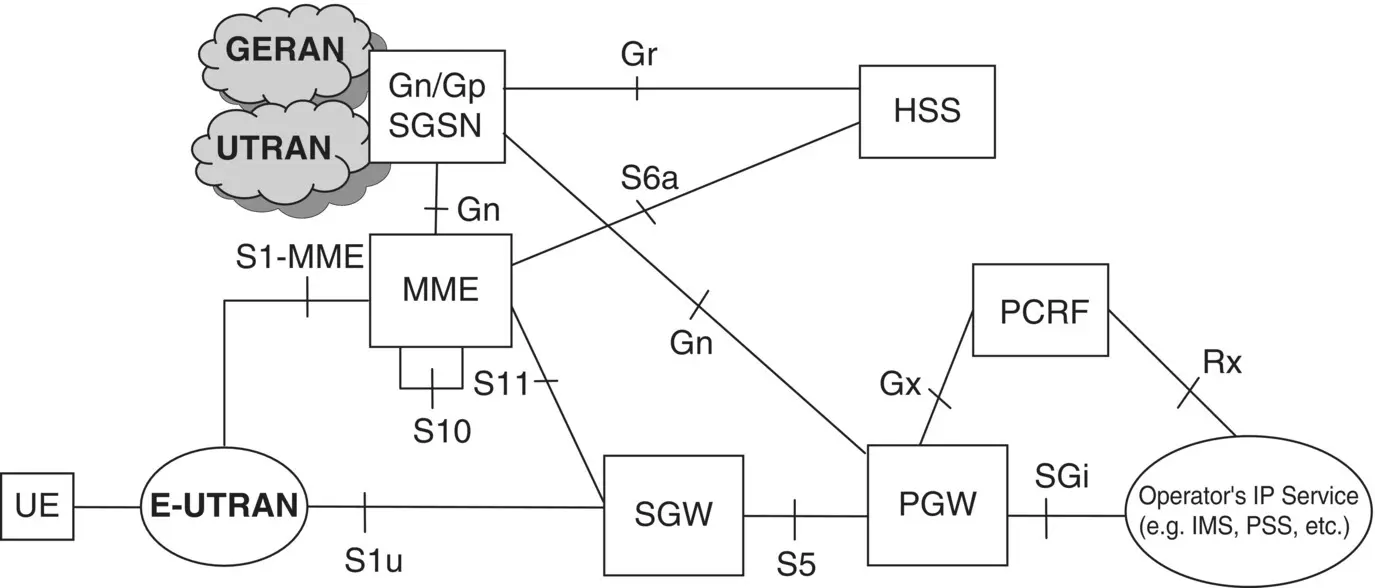
Figure 6.10 Interworking of LTE/EPS with GERAN and UTRAN through legacy network elements.
Source: © 2015. 3GPP ™ TSs and TRs are the property of ARIB, ATIS, CCSA, ETSI, TSDSI, TTA and TTC who jointly own the copyright in them. © 2015, 3GPP.
In Figure 6.10, only the representative figure for the GERAN and UTRAN networks along with the legacy SGSN is shown. The Gn interface works on top of the GTP and is used by the legacy GPRS and UMTS SGSN to communicate with the GGSN of a GPRS and UMTS network. The LTE/EPC MME communicates with the legacy SGSN over the Gn interface . LTE/EPC S‐GW also interfaces with the legacy SGSN through the Gn interface. The EPC HSS communicates with the SGSN through the existing Gr interface that works on top of the SS7 signaling protocols. On the other hand, the HSS communicates with the MME through the S6a interface that works on top of IP transport.
6.4 Interworking Between LTE/EPS and 5G Systems
In the previous section, interworking among the legacy systems has been described. To support seamless mobile communications services to subscribers during the inter‐system movement, the 5G system also provides interworking capabilities to operators. However, the 5G system supports interworking with the LTE/EPS only. For interworking between the 5G system and the LTE/EPS, the 3GPP defines a new inter core networks logical interface called N26 between the Access and Management Function (AMF) in 5G core network and the MME in the LTE/EPC network. It may be noted that interworking between the LTE/EPS and the 5G system can also take place without the presence of the N26 interface. Further, depending on the availability of the N26 interface between the 5GC/AMF and LTE/EPS MME for interworking between them, a UE can operate in one of the following modes:
Single Registration Mode, where the N26 logical interface is available between the 5GC/AMF and LTE/EPS MME.
Dual Registration Mode, where the N26 logical interface is not available between the 5GC/AMF and LTE/EPS MME.
Interworking between the 5G and the LTE/EPS with or without the N26 logical interface shall be described later in Chapter 16.
6.5 Interoperations of Networks: LTE/EPS Roaming
The roaming capability of a mobile communications network makes it possible to offer seamless voice and data services by a network operator to its subscribers while traveling outside of their home network and location and enter into a network that is run by the same or different operator in a different location. Roaming services are delivered to subscribers through the interoperation of networks operated by the same or another operator. Interoperation, in turn, is achieved through the interworking of network elements and interfaces as described in the previous sections.
In the previous Sections 6.2and 6.3, we have presented the interworking of the GSM, GPRS UMTS, and LTE/EPS networks, through the enhanced as well as legacy network elements, run by an operator. In this section, we further present the interoperations and interworking of mobile communications networks operated by different operators in different regions to provide roaming services to subscribers.
A mobile communications network operated by an operator to provide communications services in a particular area/location is known as the Public Land Mobile Network (PLMN) . A PLMN is uniquely identified, also see Section 5.2, by the combination of an MCC and MNC of an operator. Within a PLMN, an operator may provide both the voice (CS) and data services to subscribers. The PLMN in which an MS/UE is currently subscribed and registered in an LTE/EPS network is known as the home PLMN (HPLMN). The PLMN of either the same or different operator in which an MS/UE is currently roaming into and accessed the visited LTE/EPS network is known as the visiting PLMN (VPLMN).
6.5.1 Roaming Through Interoperations of Enhanced Networks Elements
In this interoperation and roaming scenario, the enhanced network elements for the LTE/EPS network are deployed both in the HPLMN and the VPLMN. There are two ways to transfer user data between the UE and the Internet in case of roaming between two different PLMNs with the enhanced network elements. To enable such roaming scenarios, new logical interfaces are used to interconnect among the network elements as described below:
Читать дальшеИнтервал:
Закладка:
Похожие книги на «Mobile Communications Systems Development»
Представляем Вашему вниманию похожие книги на «Mobile Communications Systems Development» списком для выбора. Мы отобрали схожую по названию и смыслу литературу в надежде предоставить читателям больше вариантов отыскать новые, интересные, ещё непрочитанные произведения.


Обсуждение, отзывы о книге «Mobile Communications Systems Development» и просто собственные мнения читателей. Оставьте ваши комментарии, напишите, что Вы думаете о произведении, его смысле или главных героях. Укажите что конкретно понравилось, а что нет, и почему Вы так считаете.