Rajib Taid - Mobile Communications Systems Development
Здесь есть возможность читать онлайн «Rajib Taid - Mobile Communications Systems Development» — ознакомительный отрывок электронной книги совершенно бесплатно, а после прочтения отрывка купить полную версию. В некоторых случаях можно слушать аудио, скачать через торрент в формате fb2 и присутствует краткое содержание. Жанр: unrecognised, на английском языке. Описание произведения, (предисловие) а так же отзывы посетителей доступны на портале библиотеки ЛибКат.
- Название:Mobile Communications Systems Development
- Автор:
- Жанр:
- Год:неизвестен
- ISBN:нет данных
- Рейтинг книги:5 / 5. Голосов: 1
-
Избранное:Добавить в избранное
- Отзывы:
-
Ваша оценка:
Mobile Communications Systems Development: краткое содержание, описание и аннотация
Предлагаем к чтению аннотацию, описание, краткое содержание или предисловие (зависит от того, что написал сам автор книги «Mobile Communications Systems Development»). Если вы не нашли необходимую информацию о книге — напишите в комментариях, мы постараемся отыскать её.
Mobile Communications Systems Development: A Practical Approach for System Understanding, Implementation and Deployment In-depth chapters cover the entire protocol stack from the Physical (PHY) to the Application layer, discuss theoretical and practical considerations, and describe software implementation based on the 3GPP standardized technical specifications. The book includes figures, tables, and sample computer code to help readers thoroughly comprehend the functions and underlying concepts of a mobile communications network. Each chapter includes an introduction to the topic and a chapter summary. A full list of references, and a set of exercises are also provided at the end of the book to test comprehension and strengthen understanding of the material. Written by a respected professional with more than 20 years’ experience in the field, this highly practical guide:
Provides detailed introductory information on GSM, GPRS, UMTS, and LTE mobile communications systems and networks Describes the various aspects and areas of the LTE system air interface and its protocol layers Covers troubleshooting and resolution of mobile communications systems and networks issues Discusses the software and hardware platforms used for the development of mobile communications systems network elements Includes 5G use cases, enablers, and architectures that cover the 5G NR (New Radio) and 5G Core Network
is perfect for graduate and postdoctoral students studying mobile communications and telecom design, electronic engineering undergraduate students in their final year, research and development engineers, and network operation and maintenance personnel.
Mobile Communications Systems Development — читать онлайн ознакомительный отрывок
Ниже представлен текст книги, разбитый по страницам. Система сохранения места последней прочитанной страницы, позволяет с удобством читать онлайн бесплатно книгу «Mobile Communications Systems Development», без необходимости каждый раз заново искать на чём Вы остановились. Поставьте закладку, и сможете в любой момент перейти на страницу, на которой закончили чтение.
Интервал:
Закладка:
6.2.1.2 UE Registration and Authentication
In a live network of an operator, once a UE is registered and authenticated by the LTE/EPC as part of the LTE/EPS ATTACH procedure, TS 24.301 [46], a VoLTE‐capable UE is also required to register and authenticate itself with the IMS before it can start using IMS services. For these purposes, SIP signaling messages are exchanged between the UE and the IMS. Example 6.1below describes and illustrates the flow of signaling messages, starting from registration to call establishment, conversation, and its completion, for a typical VoLTE call between two mobile devices over an IMS.
Example 6.1Illustration: UE Registration and VoLTE Call over IMS
Let us consider a typical VoLTE call performed between two UEs: UE1 and UE2. To enable a VoLTE call, the UEs are required to be registered with both the LTE EPC and IMS for the allocation of the necessary resources, for example, EPS bearers with required Quality of Service (QoS). Several steps are involved in a VoLTE call over the IMS as described below:
UE Registration with EPC and Allocation of Default Bearer with QoS Class Identifier (QCI) = 5
Figure 6.3below illustrates the allocation of a default bearer to each UE as part of its ATTACH procedure requested to the core network. The allocated default bearer has the QCI = 5, Priority =1, refer to TS 23.203 [33], with nonguaranteed bit rate (NGBR) that is used to exchange IMS signaling messages between the UE and IMS. The dotted lines in Figure 6.3indicate that some of the messages as part of the overall ATTACH procedure (which are exchanged between the UE and the EPC) are not shown in this figure. One such message is the Evolved Packet System Session Management (ESM) Information request, from EPC to UE, and its response, from UE to EPC. Using the ESM information response message, the UE provides the P‐CSCF ’ s Access Point Name (APN) in the case of the IMS.
UE Registration with IMS through Authentication
The UEs register with the IMS using the default bearer with QCI = 5 that was allocated during their registrations with EPC. To register with the IMS, a UE uses the SIP signaling message that is transferred as the user plane data over the LTE/EPS toward the IMS. P‐CSCF is connected with the P‐GW of the LTE/EPC. For a UE, the proxy CSCF is the entry and exit server in the IMS. A UE sends the APN of the P‐CSCF server in the SIP: REGISTER message to the IMS. The UE sends its authentication response details in the REGISTER message again to the IMS following the 401: Unauthorized request message from the IMS; see Figure 6.4.
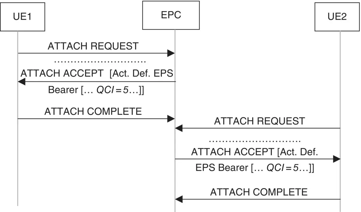
Figure 6.3 Allocation of default bearer with QCI = 5 for IMS signaling.
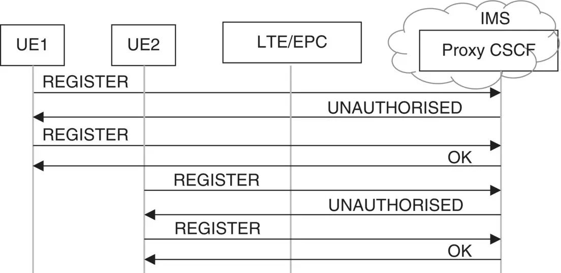
Figure 6.4 Illustration: registration of UE in an IMS.
The end‐to‐end message flow for a typical registration of a UE in an IMS is ‐ UE < ‐>eNodeB<���− > S‐GW < ‐>P‐GW < ‐>P‐CSCF. Though not shown in Figure 6.4, once the P‐CSCF receives the registration request from a UE, it is further processed by the I‐CSCF, HSS, S‐CSCF server and responds with the SIP: 200 OK messages to the registered UE.
VoLTE Call over IMS
UEs that are EPC and IMS registered can establish a voice‐over IMS to facilitate a voice call between two subscribers. The SIP signaling messages flows associated with a typical VoLTE call between two UEs – UE1 and UE2 – over IMS are illustrated in Figure 6.5. Only the P‐CSFC is shown in the call flow below, though the I‐CSCF and S‐CSCF also take part in an IMS call.
In Figure 6.5, the E‐UTRAN and EPC/NAS‐related signaling messages that are exchanged with the UEs are not shown for simplicity of the flows. The INVITE method carries the calling and called party ’ s number and is used to establish a session between the two UEs. As shown in this figure, the EPS allocates a dedicated bearer with QCI = 1, Priority = 2, refer to TS 23.203 [33], with a guaranteed bit rate (GBR) over which the voice conversation takes place between the users. The establishment of a dedicated bearer for voice conversation purposes is intimated to the called UE through SIP:UPDATE method, following which it sends the SIP:RINGING status to the caller UE.
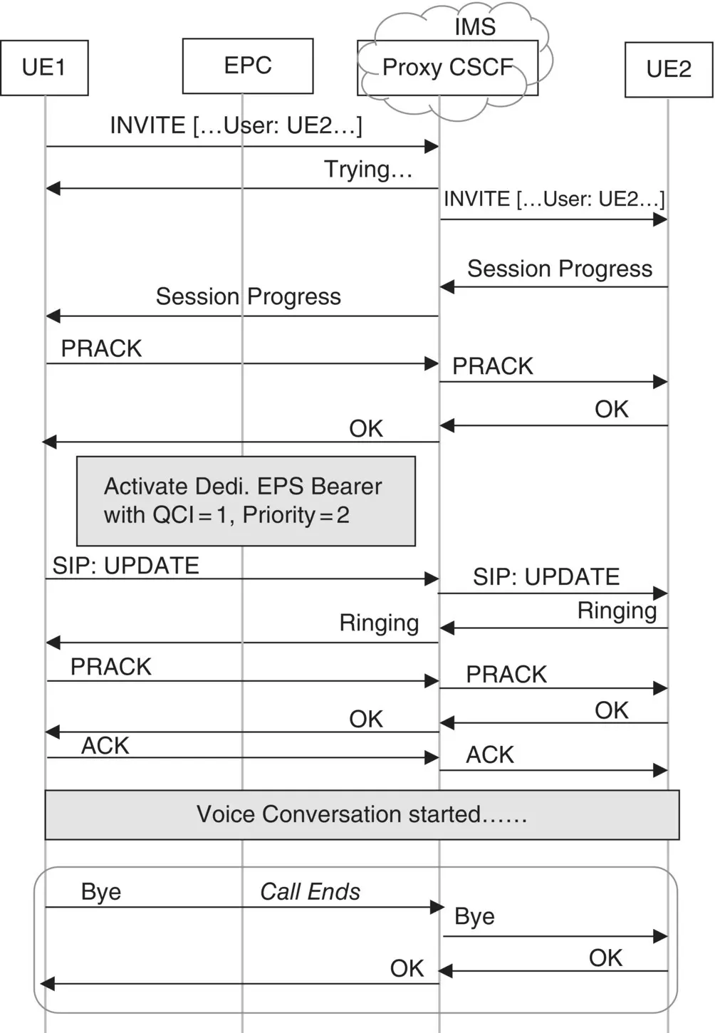
Figure 6.5 Illustration: VoLTE call between IMS registered UEs.
The IMS for VoLTE described above will be also the foundation for the voice services over the 5G system with essential extensions added, as part of the 3GPP Release 15, over some of the existing logical interfaces, such as the Rx, Sh.
6.2.2 Interworking for VoLTE Call Through LTE/EPS: SRVCC
The provision of a handover of an existing VoLTE call to a legacy GERAN or UTRAN system is known as the SRVCC (refer to TS 23.216 [35]) because of the single RAT capability of a UE at a given time only. Interworking through the SRVCC scenario is a bit similar to the one described in Section 6.2.1. However, there is a difference from the E‐UTRAN UE capability point of view. SRVCC interworking scenario is suitable for an LTE UE having only one radio capability at a given time. Because of this, a VoLTE call over the IMS is required to be handed over to the legacy GERAN or UTRAN system for the continuation of the IMS voice call. The interworking of network elements, with IMS, for the SRVCC feature is illustrated in Figure 6.6.
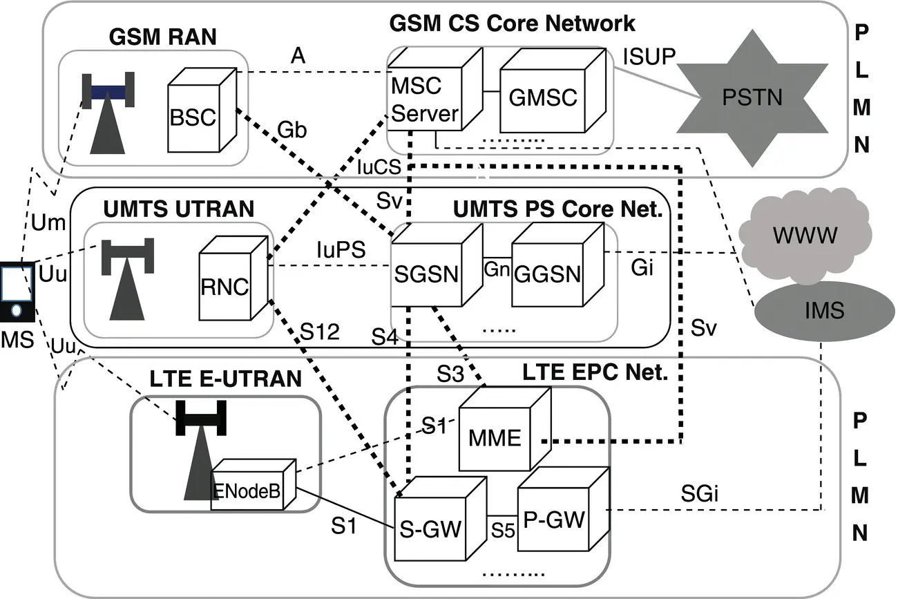
Figure 6.6 Illustration: legacy and LTE network interworking for VoLTE call HO through SRVCC.
For the SRVCC capability to be realized, a new logical interface Sv, refer to TS 29.280 [71], is defined between the
MME and the MSC server and
MME and SGSN, as shown above.
Figure 6.7further illustrates the SRVCC HO of an LTE/EPS IMS voice call made by the VoLTE user A to a PSTN user B.
In Figure 6.7, user A moved to a legacy 2G/3G coverage area. As the user moved away from the LTE coverage area and approaches a 2G/3G coverage area, the eNodeB detects a better signal level from the 2G/3G networks. UE sends the measurements reports to the eNodeB which in turn sends an SRVCC HO request to the MME. In Figure 6.7, the signaling and traffic paths are shown prior to and after the SRVCC HO. All the subsequent signaling and data communication takes place through the legacy network MSC server after the SRVCC HO is completed.
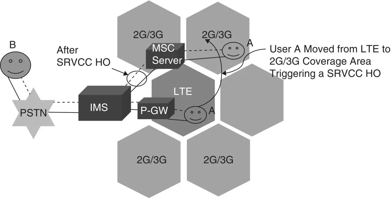
Figure 6.7 Illustration: VoLTE call HO through SRVCC feature.
How does SRVCC work?
Indication of Feature Support
An LTE UE indicates its SRVCC capability information through the class mark and network capability information sent along with the ATTACH Request message, refer to TS 24.301 [46], to the MME. MME indicates the SRVCC capability of a UE through the SRVCC operation possible IE in the INITIAL CONTEXT SETUP REQUEST MESSAGE, refer to TS 36.413 [97], to the eNodeB. MME may also request the SRVCC capability of a UE by sending the message UE Radio Capability Match Request (see Section 5.3.14 TS 23.401 [39] ) to the UE through the eNodeB. Any subsequent changes in the SRVCC capability of a UE are also updated to the HSS by the MME.
Читать дальшеИнтервал:
Закладка:
Похожие книги на «Mobile Communications Systems Development»
Представляем Вашему вниманию похожие книги на «Mobile Communications Systems Development» списком для выбора. Мы отобрали схожую по названию и смыслу литературу в надежде предоставить читателям больше вариантов отыскать новые, интересные, ещё непрочитанные произведения.


Обсуждение, отзывы о книге «Mobile Communications Systems Development» и просто собственные мнения читателей. Оставьте ваши комментарии, напишите, что Вы думаете о произведении, его смысле или главных героях. Укажите что конкретно понравилось, а что нет, и почему Вы так считаете.