Trinath Sahoo - Root Cause Failure Analysis
Здесь есть возможность читать онлайн «Trinath Sahoo - Root Cause Failure Analysis» — ознакомительный отрывок электронной книги совершенно бесплатно, а после прочтения отрывка купить полную версию. В некоторых случаях можно слушать аудио, скачать через торрент в формате fb2 и присутствует краткое содержание. Жанр: unrecognised, на английском языке. Описание произведения, (предисловие) а так же отзывы посетителей доступны на портале библиотеки ЛибКат.

- Название:Root Cause Failure Analysis
- Автор:
- Жанр:
- Год:неизвестен
- ISBN:нет данных
- Рейтинг книги:5 / 5. Голосов: 1
-
Избранное:Добавить в избранное
- Отзывы:
-
Ваша оценка:
Root Cause Failure Analysis: краткое содержание, описание и аннотация
Предлагаем к чтению аннотацию, описание, краткое содержание или предисловие (зависит от того, что написал сам автор книги «Root Cause Failure Analysis»). Если вы не нашли необходимую информацию о книге — напишите в комментариях, мы постараемся отыскать её.
Provides the knowledge and failure analysis skills necessary for preventing and investigating process equipment failures Root Cause Failure Analysis: A Guide to Improve Plant Reliability
Root Cause Failure Analysis: A Guide to Improve Plant Reliability
Root Cause Failure Analysis — читать онлайн ознакомительный отрывок
Ниже представлен текст книги, разбитый по страницам. Система сохранения места последней прочитанной страницы, позволяет с удобством читать онлайн бесплатно книгу «Root Cause Failure Analysis», без необходимости каждый раз заново искать на чём Вы остановились. Поставьте закладку, и сможете в любой момент перейти на страницу, на которой закончили чтение.
Интервал:
Закладка:
One note of caution is that the type of fracture, ductile, or brittle should be compared with the nature of the material. There are some instances where brittle fractures appear in normally ductile materials. This indicates that either the load was applied very rapidly or some change has occurred in the material, such as low temperature embrittlement, and the material is no longer ductile. An example of this was a low carbon steel clip used to hold a conduit in position in a refrigerated (−50 °F) warehouse. The clip was made from a very ductile material, yet it failed in a brittle manner. The investigation showed it had been hit by a hammer, a blow that would have deformed it at normal temperatures.
In a brittle overload failure, separation of the two halves isn’t quite instantaneous, but proceeds at a tremendous rate, nearly at the speed of sound in the material. The crack begins at the point of maximum stress, then grows across by cleavage of the individual material grains. One of the results of this is that the direction of the fracture path is frequently indicated by chevron marks that point toward the origin of the failure.
Brittle vs. Ductile Fracture characteristics
Ductile materials‐ extensive plastic deformation and energy absorption (“toughness”) before fracture.
Brittle materials‐ little plastic deformation and low energy absorption before fracture.
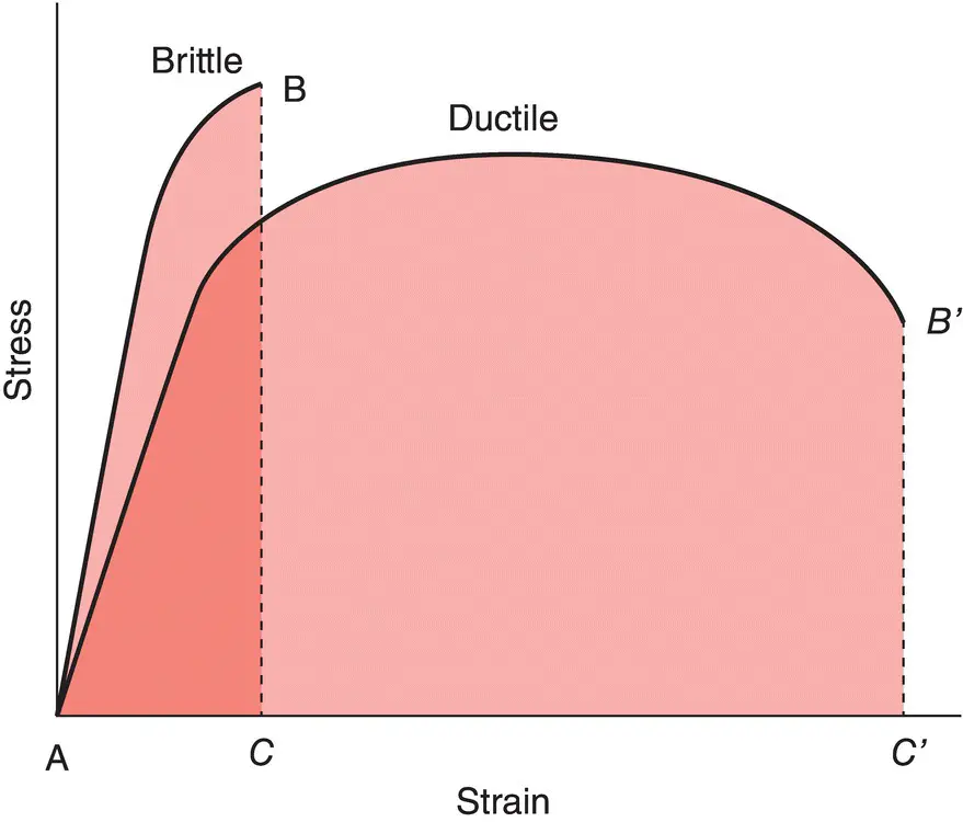
Figure 5.2Stress–strain curve of brittle and ductile material.
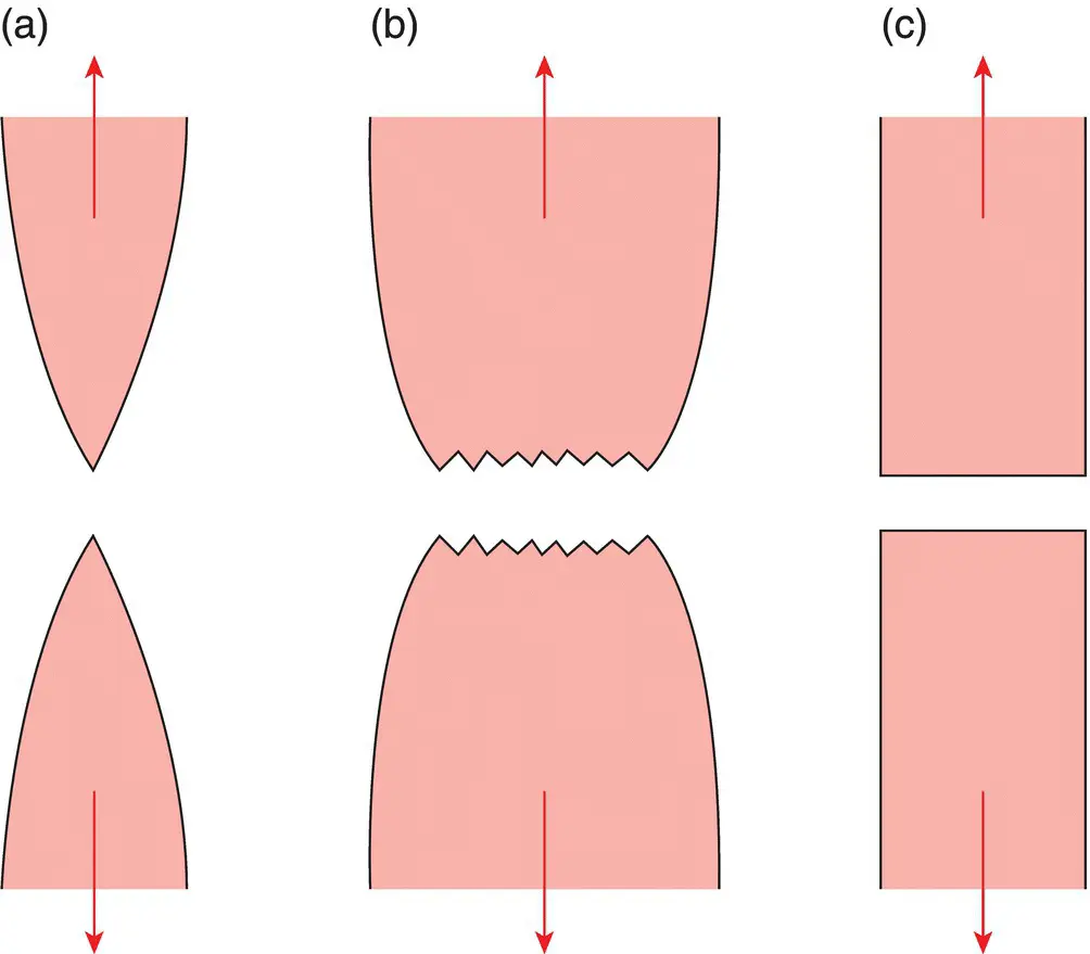
Figure 5.3Ductile vs brittle fracture. (a) Very ductile, soft metals (e.g., Pb, Au) at room temperature, other metals, polymers, and glasses at high temperature. (b) Moderately ductile fracture, typical for ductile metals. (c) Brittle fracture, cold metals, ceramics.
Ductile Fracture
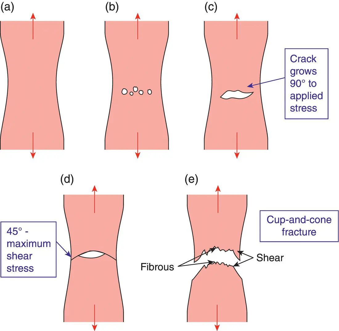
Figure 5.4Different stages before ductile fracture. (a) Necking (b) formation of microvoids (c) coalescence of microvoids to form a crack (d) crack propagation by shear deformation (e) fracture.
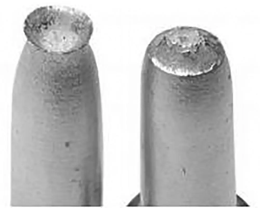
Figure 5.5Cup and cone fracture in Al.
Source : Callister, William D. and Rethwisch, David G. (2009). Materials Science and Engineering: An Introduction, 8e. Wiley.
Brittle Fracture
No appreciable plastic deformation
Crack propagation is very fast
Crack propagates nearly perpendicular to the direction of the applied stress
Crack often propagates by cleavage – breaking of atomic bonds along specific crystallographic planes (cleavage planes).
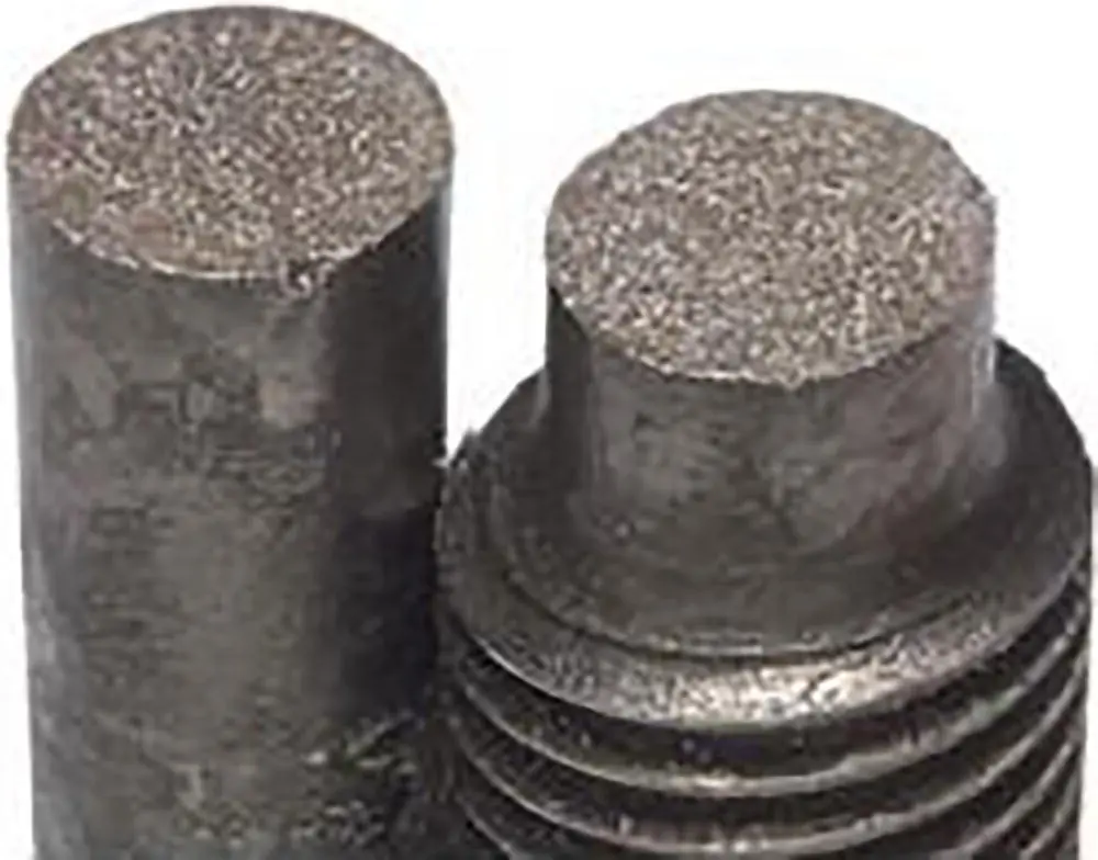
Figure 5.6Brittle fracture in a mild steel.
Source : Callister, William D. and Rethwisch, David G. (2009). Materials Science and Engineering: An Introduction, 8e. Wiley.
Example: Failure of a Pipe
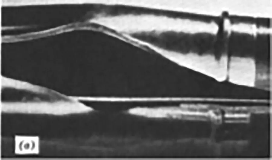
Figure 5.7Ductile failure: ‐one piece ‐large deformation (after some amount of plastic deformation).
Source : Colangelo, Vito J. and Heiser, Francis A. (1987). Analysis of Metallurgical Failures. 2e. Wiley.
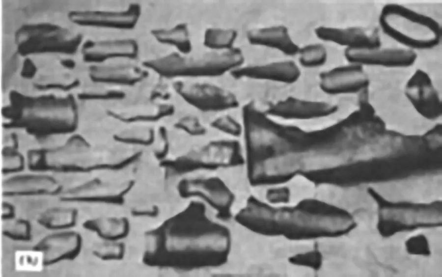
Figure 5.8Brittle failure: ‐many pieces ‐small deformation, (even when the stress is within the elastic range).
Depending on the ability of material to undergo plastic deformation before the fracture two fracture modes can be defined – ductile or brittle. Ductile fracture is characterized by large amounts of plastic deformation. Proportionally large amounts of energy will therefore be required to induce this fracture. When designing a structure, it is usually preferable for the material to fail in a ductile manner as there will be sufficient warning (evidence of deformation) before the final failure occurs. In a brittle fracture, little plastic deformation and low energy absorption before fracture take place.
Ductile fracture‐most metals (not too cold):
Extensive plastic deformation ahead of crack.
Crack is “stable”.
Resists further extension unless applied stress is increased.
Stages in Ductile Fracture
Necking
Cavity formation (micro cracks)
Crack formation
Crack propagation
Fracture
Brittle Fracture Characteristics
Takes place without any appreciable plastic deformation and by rapid crack propagation.
Direction of crack motion is nearly perpendicular to the direction of applied tensile stress.
Flat surface.
Brittle fracture‐ceramics, ice, cold metals:
Relatively little plastic deformation.
Crack is “unstable.”
propagates rapidly without increase in applied stress.
Origin of Fractures (Ductile and Brittle)
Every structure has a load limit beyond which it is considered unsafe. An applied load that exceeds this limit is known as overload. When a component fails because due to a single application of a load greater than the strength of the component, it is termed as overload failure. The nature of fracture arising due to overload failure could either be ductile or brittle or a combination of the two.
In general, ductile fractures are associated with metal flow at failure zone due to plastic deformation and fibrous‐surface appearance. In brittle fractures, plastic deformation is almost absent and the surface shows irregular bright facets of a cleavage type. Establishing the origin of a fracture is essential in failure analysis, and the location of the origin determines which measures should be taken to prevent a repetition of the fracture. The fracture‐surface characteristics that show the direction of crack propagation (and conversely, the direction toward the origin) include features such as chevron marks, crack branching, and river patterns. Features that help identify the crack origin include concentric fibrous marks, radial marks, and beach marks. By a study of these features, crack progress can be traced back to the point of origin, and then, it can be ascertained whether the crack was initiated by an inclusion, a porous region, a segregated phase, a corrosion pit, a machined notch, a forging lap, a nick, a mar, or another type of discontinuity, or was simply the result of overloading.
Some of the questions that should be raised concerning the nature, history, functions, and properties of the fractured part, and the manner in which it interacts with other parts, to find out root cause of failure are‐
Читать дальшеИнтервал:
Закладка:
Похожие книги на «Root Cause Failure Analysis»
Представляем Вашему вниманию похожие книги на «Root Cause Failure Analysis» списком для выбора. Мы отобрали схожую по названию и смыслу литературу в надежде предоставить читателям больше вариантов отыскать новые, интересные, ещё непрочитанные произведения.


Обсуждение, отзывы о книге «Root Cause Failure Analysis» и просто собственные мнения читателей. Оставьте ваши комментарии, напишите, что Вы думаете о произведении, его смысле или главных героях. Укажите что конкретно понравилось, а что нет, и почему Вы так считаете.