Trinath Sahoo - Root Cause Failure Analysis
Здесь есть возможность читать онлайн «Trinath Sahoo - Root Cause Failure Analysis» — ознакомительный отрывок электронной книги совершенно бесплатно, а после прочтения отрывка купить полную версию. В некоторых случаях можно слушать аудио, скачать через торрент в формате fb2 и присутствует краткое содержание. Жанр: unrecognised, на английском языке. Описание произведения, (предисловие) а так же отзывы посетителей доступны на портале библиотеки ЛибКат.

- Название:Root Cause Failure Analysis
- Автор:
- Жанр:
- Год:неизвестен
- ISBN:нет данных
- Рейтинг книги:5 / 5. Голосов: 1
-
Избранное:Добавить в избранное
- Отзывы:
-
Ваша оценка:
Root Cause Failure Analysis: краткое содержание, описание и аннотация
Предлагаем к чтению аннотацию, описание, краткое содержание или предисловие (зависит от того, что написал сам автор книги «Root Cause Failure Analysis»). Если вы не нашли необходимую информацию о книге — напишите в комментариях, мы постараемся отыскать её.
Provides the knowledge and failure analysis skills necessary for preventing and investigating process equipment failures Root Cause Failure Analysis: A Guide to Improve Plant Reliability
Root Cause Failure Analysis: A Guide to Improve Plant Reliability
Root Cause Failure Analysis — читать онлайн ознакомительный отрывок
Ниже представлен текст книги, разбитый по страницам. Система сохранения места последней прочитанной страницы, позволяет с удобством читать онлайн бесплатно книгу «Root Cause Failure Analysis», без необходимости каждый раз заново искать на чём Вы остановились. Поставьте закладку, и сможете в любой момент перейти на страницу, на которой закончили чтение.
Интервал:
Закладка:
5 Metallurgical Failure
Many a times unanticipated equipment failures do occur for a variety of reasons. These events often become too costly as well as disruptive to plant operations and may also have safety implications. To minimize the frequency and severity of such failures, it is necessary for personnel who have equipment responsibility to understand the failures and to confront their causes. Potential causes of the failure of the components and their mechanism are numerous. Therefore, procedure of the failure analysis of each failed component should be different and the same must be developed after giving proper thought on possible sequence of events before failure along with proper evaluation of the situation and consideration of material, manufacturing process, service history and actual working condition, etc. Since the failure analysis involves lot of efforts, time and use of resources therefore at the end of analysis failure analyst should be in a position to come out with few most potential causes of the failure so that suitable recommendations can be made to avoid reoccurrence of the similar failure.
It may sound a little far‐fetched, but experts say that the causes for more than 90% of all plant failures can be detected with a careful physical examination using low power magnification and some basic physical testing. Inspection of the failure component will show the forces involved, whether the load applied cyclically or was single overload, the direction of the critical load, and the influence of outside forces such as residual stresses or corrosion. Then, accurately knowing the physical roots of the failure, you can pursue both the human errors and the latent causes of these physical roots.
In this chapter, an overview of the processes involved in a typical metallurgical failure analysis is provided. The discussion describes various failure mechanisms in metals that can be examined, some of the tests and processes that are used in an analysis, for failed components.
The metallurgical failure analysis can be defined as a scientifically based systematic laboratory examination of metallurgical evidence and the gathering of background information related to an equipment failure. This analysis helps in establishing the cause of the failure. Because the approach to the failure analysis is usually determined by the nature of the failure, all analyses do not require the same procedure. Laboratory procedures focus on the failed equipment itself and most commonly consist of general and detailed macrophotography, metallo‐graphic examination, chemical analysis of the failed part and of any extraneous or foreign materials present, mechanical property determinations, fractographic examination, and others.
Understanding the Basics
Before explaining how to diagnose a failure, we should review the effects of stress on a component. When a load is put on a part, it distorts. In a sound design the load isn’t excessive, the stress doesn’t exceed the “yield point,” and the part deforms elastically, i.e., when the load is released the part returns to its original shape. This is shown in Figure 5.1, a “stress–strain” diagram that shows the relationship between loads and deformation. In a good design, the part operates in the elastic range, the area between the origin and the yield strength. Beyond this point, the part will be permanently deformed, even greater increases in load will cause the part to break.
Elastic Limit
The elastic limit is the limit beyond which the material will no longer go back to its original shape when the load is removed, or it is the maximum stress that may be developed such that there is no permanent or residual deformation when the load is entirely removed.
Elastic and Plastic Ranges
The region in stress–strain diagram from O to P is called the elastic range. The region from P to R is called the plastic range.
Yield Point
Yield point is the point at which the material will have an appreciable elongation or yielding without any increase in load.
Ultimate Strength
The maximum ordinate in the stress–strain diagram is the ultimate strength or tensile strength.
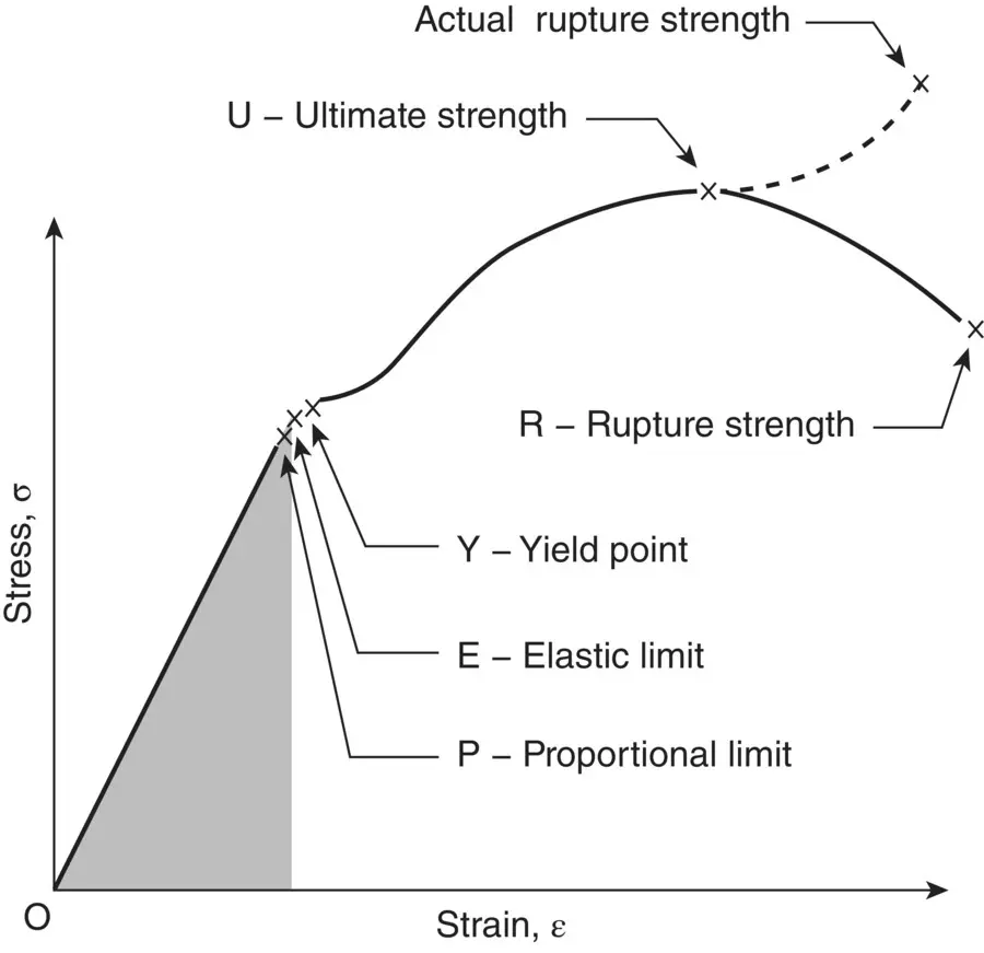
Figure 5.1 Stress–strain diagram of a medium‐carbon structural steel.
Rapture Strength
Rapture strength is the strength of the material at rupture. This is also known as the breaking strength.
Elastic Deformation
Elastic deformation occurs when stiffness of the component is less and the same is primarily determined by modulus of elasticity and cross section. Elastic deformation can lead to the failure of mechanical components especially in high precision assemblies and machinery where even small elastic deformation under operating conditions is not acceptable.
Plastic Deformation
Excessive plastic deformation of the mechanical components can lead to the failure in two conditions (i) externally applied stress is beyond the yield strength limit and (ii) component is subjected to applied stress lower than yield stress but exposed to high temperature conditions enough to cause creep.
To avoid the failure by plastic deformation owing to externally applied stress more than yield strength, the cross section should be designed after taking proper factor of safety and considering the yield strength of materials of which component is to be made. For mechanical components that are expected to be exposed in high temperature, creep resistant materials should be selected so that under identical load condition, low steady‐state creep rate of creep‐resistant materials can allow desired longer creep life.
Identification of Types of Failures
Failure analysis is separated into two distinct parts, the first being the mode of failure, and second, the cause of failure. The mode is the failure process, and the cause is the part that can be altered or changed to prevent future occurrence. Some commonly recognized failure modes are as follows:
Fracture (Ductile and Brittle)
Fatigue (mechanical and thermal)
Stress Corrosion
Hydrogen Damage
Corrosion
Wear and Erosion
Fracture – Ductile Overload vs. Brittle Overload Failures “Ductile failure” is one where there is a great deal of distortion of the failed part. Commonly, a ductile part fails when it distorts and can no longer carry the needed load, like an overloaded steel coat hanger. However, some ductile parts break into two pieces and can be identified because there is a great deal of distortion around the fracture face, similar to what would happen if you tried to put too much load on a low carbon steel bolt.
The term “brittle fracture” is used when a part is overloaded and breaks with no visible distortion. This can happen because the material is very brittle, such as gray cast iron or hardened steel, or when a load is applied extremely rapidly to a normally ductile part. A severe shock load on the most ductile piece can cause it to fracture like glass.
An important point about failures is that the way the load is applied, i.e., the direction and the type, can be diagnosed by looking at the failure face. A crack will always grow perpendicular to the plane of maximum stress. Below we show examples of the difference in appearance between ductile overload and brittle overload failures.
We know we can look at an overload failure and knowing the type of material, tell the direction of the forces that caused the failure. Common industrial materials that are ductile include most aluminum and copper alloys, steels and stainless steels that are not hardened, most nonferrous metals, and many plastics. Brittle materials include cast irons, hardened steel parts, high strength alloyed nonferrous metals, ceramics, and glass.
Читать дальшеИнтервал:
Закладка:
Похожие книги на «Root Cause Failure Analysis»
Представляем Вашему вниманию похожие книги на «Root Cause Failure Analysis» списком для выбора. Мы отобрали схожую по названию и смыслу литературу в надежде предоставить читателям больше вариантов отыскать новые, интересные, ещё непрочитанные произведения.


Обсуждение, отзывы о книге «Root Cause Failure Analysis» и просто собственные мнения читателей. Оставьте ваши комментарии, напишите, что Вы думаете о произведении, его смысле или главных героях. Укажите что конкретно понравилось, а что нет, и почему Вы так считаете.