At the end of the IP session, when the mobile enters the standby state, the SMF releases the session by removing the context at the UPF.
In the event of incoming packets, if the mobile is in the idle state, the SMF sends a notification to the AMF (Downlink Data Notification).
1.2.4. UPF (User Plane Function)
The UPF (User Plane Function) manages the routing of user traffic and implements traffic filtering functions.
The PSA UPF is the traffic gateway connecting the 5GC network to the DN (Data Network). The PSA constitutes the anchor point for inter-UPF mobility.
The UPF is the anchor point for traffic when the mobile is moving from one NG-RAN node to another.
The UPF measures the quantity of data consumed for each UE.
The UPF can also implement traffic optimization functions and NAT (Network Address Translation), either from a private IPv4 address to a public IPv4 address, or from an IPv4 address to an IPv6 address and vice versa.
When the UPF receives data from the DN:
1 – in the absence of a routing context concerning the incoming flow, the UPF informs the SMF. The UPF either stores the data or transmits it to the SMF;
2 – in the presence of a routing context stored at the UPF level concerning the incoming flow, the flow is either transmitted to an NG-RAN node or to another UPF.
The UPF implements traffic routing rules by configuring the DSCP field of the IP based on the QFI. The QFI is defined by QoS rules which are injected by the SMF to the UPF when establishment of a session is requested. For each incoming piece of data, the UPF performs a traffic inspection (DPI (Deep Packet Inspection)) and classifies the packets into IP flow groups according to the SDF (Service Data Flow) service templates.
The UPF is a branch point supporting the multi-homing function.
The UPF performs replications of the mobile traffic data within the framework of lawful interception.
1.3. Functional separation between the NG-RAN radio interface and the 5G core network
The AMF is in charge of managing the 5G core network and services. It authenticates and registers each mobile and manages their mobility. Once registered, the AMF authorizes services according to the user’s profile.
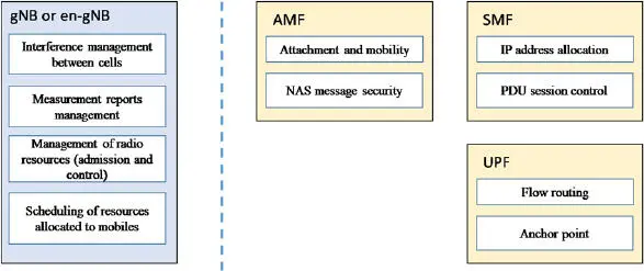
Figure 1.7summarizes the functions managed on the NG-RAN and on the 5GC.

Figure 1.7. The functional separation between NG-RAN and 5GC
1.3.1. Mobile identities
1.3.1.1. The identity of the mobile at the level of the AMF
Registration procedure occurs when the mobile switches on. If authentication succeeds, the state of the mobile changes from the RM-DEREGISTERED state to the RM-REGISTERED state and a user context (UE Context) is created on the AMF.
During the registration procedure, the AMF registers the IMSI (International Mobile Subscriber Identity) from its private identifier SUPI or private and hidden identifier SUCI.
The SUPI and SUCI identifiers allow the core network to identify the subscription associated with the mobile. The identifier format matches with the description of the NAI (Network Access Identifier) in order to be compatible with the DNS (Domain Name Server) servers by respecting the RFC7542 specification.
The SUPI identifier consists of two fields: the type of SUPI identifier (IMSI Identifier (International Mobile Subscriber Identity) or an identifier specific to the operator network) and the IMSI identity value or specific NAI value.
The SUCI identifier is made up of six fields defined as follows ( Figure 1.8):
type .hni .rid .schid .hnkey .out .

Figure 1.8. The fields of the SUCI identifier
The SUPI type value is used to indicate whether the SUPI identifier corresponds to the IMSI identity (type = 0) or a network-specific identifier (type = 1).
The hni field corresponds to the country code (MCC (Mobile Network Country)) and the operator code (MNC (Mobile Network Code)).
The ri field is defined over four digits. The default value is 0, but a specific value is used to identify on which partition of the UDR database the mobile subscription is stored (in the case of UDR, composed of different memory stacks).
The hnkey field identifies the key used for the encryption of the SUCI identifier.
The outfield is the result of the encryption of the mobile’s IMSI identity (MSIN (Mobile Subscriber Identification Number)) including the message authentication value (MAC (Message Authentication Code)).
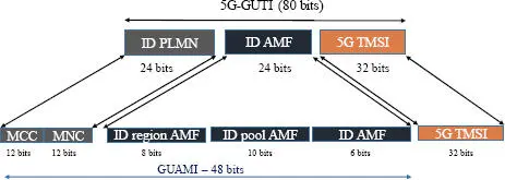
After authentication, the AMF provides a 5G-GUTI. Each 5G-GUTI is unique. This 5G-TMSI identifier is concatenated with the AMF identifier, in order to constitute the 5G-GUTI identifier ( Figure 1.9).
The GUAMI identity corresponds to the AMF address. The GUAMI identity is the concatenation of the identity of the PLMN and the identity of the AMF:
= .
The 5G-S-TMSI identifier combines the AMF identity (AMF pool ID and pointer) as well as the 5G-TMSI identifier:
<5G-S-TMSI> = <5G-TMSI>.
The 5G-S-TMSI identifier is used as a radio identification for paging notifications.

Figure 1.9. The fields of the 5G-GUTI identifier
Once registered, the connection state of the mobile at the AMF level is either the connected state (CM-CONNECTED) or the standby state (CM-IDLE).
In the CM-CONNECTED state, a NAS connection is established between the mobile and the AMF function. Because the NAS connection is encapsulated in the RRC message, the mobile is both in the CM-CONNECTED state with the AMF and in the RRC_CONNECTED state with the NG-RAN node. The NG-RAN node creates a UE context with RNTI (Radio Network Temporary Identifier).
After a period of inactivity, the NG-RAN node can:
1 – suspend the radio connection. The mobile goes to the RRC_INACTIVE state, the context is kept by the NG-RAN node and the UE context is kept at the AMF level (the mobile is still in the CM-CONNECTED state);
2 – release the radio bearer and remove the UE context. The mobile goes to the RRC_IDLE state and the UE context goes to the CM_IDLE state at the AMF level.
In the RRC_IDLE state, the mobile listens to the information sent by the NG-RAN node. In the RRC_IDLE state, cell reselection is managed by the mobile.
1.3.1.2. The identity of the mobile at the level of NG-RAN
Each NG-RAN node manages a set of mobiles. The NG-RAN node assigns a specific RNTI radio identifier to each mobile. A broadcast identifier is also used to broadcast information like the common control channel and information system.
Consequently, for any mobile in the standby mode, the NG-RAN node uses the following radio identities:
1 – P-RNTI (Paging) to send a paging request;
2 – SI-RNTI (System Information) to broadcast SIB messages;
3 – RA-RNTI (Random) to identify a mobile when requesting radio access (random access procedure; see Chapter 3);
4 – TC-RNTI (Temporary Cell) which helps to retrieve the information exchanged during the connection procedure, following the random procedure.
If the mobile is in the RRC_INACTIVE state (in the standby mode) on the NG-RAN, its identifier is called I-RNTI.
Читать дальше


