Active Electrical Distribution Network
Здесь есть возможность читать онлайн «Active Electrical Distribution Network» — ознакомительный отрывок электронной книги совершенно бесплатно, а после прочтения отрывка купить полную версию. В некоторых случаях можно слушать аудио, скачать через торрент в формате fb2 и присутствует краткое содержание. Жанр: unrecognised, на английском языке. Описание произведения, (предисловие) а так же отзывы посетителей доступны на портале библиотеки ЛибКат.
- Название:Active Electrical Distribution Network
- Автор:
- Жанр:
- Год:неизвестен
- ISBN:нет данных
- Рейтинг книги:5 / 5. Голосов: 1
-
Избранное:Добавить в избранное
- Отзывы:
-
Ваша оценка:
Active Electrical Distribution Network: краткое содержание, описание и аннотация
Предлагаем к чтению аннотацию, описание, краткое содержание или предисловие (зависит от того, что написал сам автор книги «Active Electrical Distribution Network»). Если вы не нашли необходимую информацию о книге — напишите в комментариях, мы постараемся отыскать её.
Discover the major issues, solutions, techniques, and applications of active electrical distribution networks with this edited resource Active Electrical Distribution Network: A Smart Approach
Active Electrical Distribution Network: A Smart Approach
Active Electrical Distribution Network — читать онлайн ознакомительный отрывок
Ниже представлен текст книги, разбитый по страницам. Система сохранения места последней прочитанной страницы, позволяет с удобством читать онлайн бесплатно книгу «Active Electrical Distribution Network», без необходимости каждый раз заново искать на чём Вы остановились. Поставьте закладку, и сможете в любой момент перейти на страницу, на которой закончили чтение.
Интервал:
Закладка:
As per the proposed methodology, any one of the tie switches is closed and one of the sectionalizing switches constituting the loop is made open in the first step. Generally, the tie switch across which the voltage difference is highest among all the tie switches and is also more than a specified value is preferred to be closed first. For example, in the network shown in Table 2.1, tie switch 36 will be closed first as the voltage difference across it is highest among all the ties switches. Similarly, the sectionalizing switch that is opened first is the one that is connected to any one bus between the two supporting buses of the tie switch; generally the bus with the lower voltage is preferred. The reconfigured network obtained with the closing of the tie switch and opening of the sectionalizing switch will be considered as the base case for running the load flow. Suppose x 1is the total technical loss (I 2R) taking place in the network for the first base case, as obtained from the load flow. In the next step, the presently open sectionalizing switch will be closed and its adjacent sectionalizing switch in the same loop will be open. For this second reconfiguration, again the load flow will be run and the above parameters will be observed while checking for all different constraints explained above. Suppose the total technical loss (I 2R) obtained in this case is x 2. If x 2is greater than x 1, then the first reconfiguration will be the best reconfiguration corresponding to tie switch 1. However, if x 2is less than x 1, then similar steps will be repeated by closing the presently opened sectionalizing switch while simultaneously opening the next adjacent sectionalizing switch within the same loop. This process will be repeated until a reconfiguration is obtained for which the value of the total technical loss (I 2R) is more than its current previous value. Suppose the process continued for n th number of sectionalizing switches in the loop and xn is the corresponding technical loss (I 2R). Let this xn obtained from n th reconfigurations is found to be more than its previous value, i.e. xn- 1. Then the process will be stopped and ( n – 1)th reconfigurations will be considered as the best reconfiguration corresponding to tie switch 1.
Now in the next step, considering the best reconfiguration corresponding to tie switch 1 as the next base case, a similar process will be adopted for tie switch 2 and the respective optimal reconfiguration, and a corresponding total technical loss (I 2R) will be obtained. Tie switch 2 will be selected by using the same procedure as adopted for selecting tie switch 1 while considering the remaining tie switches other than tie switch 1. In the above selection of tie switch 2, the load flow data obtained from the latest reconfiguration, i.e. the best reconfiguration corresponding to tie switch 1, will be used. The final reconfiguration obtained by practicing all the procedures adopted in the case of tie switch-1 will be considered as the best reconfiguration corresponding to tie switch 2.
In the next step, the best reconfiguration corresponding to tie switch 2 will be considered as the base network and a similar process will be carried out for other remaining tie switches and their respective optimal configuration, and a corresponding total technical loss (I 2R) will be obtained. The reconfiguration that will be obtained from the last step by practicing the above explained procedure will be considered as the optimal network reconfiguration.
From the above explanation, it can be concluded that a large number of steps are required for obtaining each best reconfiguration corresponding to a particular tie switch. Hence the process of network reconfiguration becomes a complicated, combinatorial, non-differentiable, constrained optimization problem. There are even networks where millions of nodes are used. For such networks, investigating all possible options is impractical. The time required to calculate the total technical loss (I 2R) is also too huge. Therefore, it is essential to develop some trick for reducing the number of steps involved and the time required for calculating technical loss. Hence, heuristic techniques are thought to be the most suitable techniques for the network reconfiguration process.
The main objective while implementing network reconfiguration is to minimize the technical loss. Hence the objective function for the network reconfiguration problem is a loss function and is required to be minimized. While optimizing this objective function, different technical and non-technical constraints are required to be addressed, which will now be discussed.
2.6.1 Objective Function
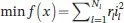
The objective is to minimize the system total technical loss (I 2R) described by:
 (2.1)
(2.1)
where N l= number of lines in the network r l= resistance of the line l i l= current flowing through line l
2.6.2 Constraints
1. Bus voltage limit:
 (2.2)
(2.2)
2. Line limits:
The current flowing through any line (i l) should not exceed the current limit of that line (i lmax).
 (2.3)
(2.3)
3. Radiality:
To ensure the radiality, the following assessment parameters are being used
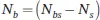
The number of loops while closing all different switches must be:
 (2.4)
(2.4)
N b= total number of branches
N bs= total number of buses
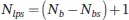
Number of branches should be:
 (2.5)
(2.5)
N bs= number of buses
N s= number of sources
All the loads should get a supply every time of reconfiguration.
The use of heuristic approaches can reduce the complexity of the network reconfiguration problem. In this chapter, a heuristic approach has been used to solve network reconfiguration problems. The following points show the detail outlines of the used heuristic algorithm.
2.6.3 Algorithm
1 Read the system input data required for load flow.
2 Run the load flow program for the distribution network and compute the power loss and voltages at various nodes.
3 Calculate the differences in voltages ΔVtie(x) between the two buses across which different tie switches are placed to be connected; x = 1, 2, 3, … Stie, where Stie = number of tie switches.
4 Form a table for the above calculated voltage differences for all of the tie switches.
5 From the above table, select the tie switch for which the value of ΔVtie(x) is maximum. Suppose it is the tie switch ‘n’ such that (ΔVtie,max = ΔVtie(n)).
6 Compare the value of the (ΔVtie,max) with a set threshold value (θ). If ΔVtie,max is greater than the threshold value, go to the next step, else stop.
7 Compare the node voltages of the two nodes across which the tie switch ‘n’ is connected. Select the node with the smallest value. Let it be the node ‘m’ with node voltage Vm.
8 Close the tie switch ‘n’ and simultaneously open the sectionalizing switch connected to node ‘m’.
Читать дальшеИнтервал:
Закладка:
Похожие книги на «Active Electrical Distribution Network»
Представляем Вашему вниманию похожие книги на «Active Electrical Distribution Network» списком для выбора. Мы отобрали схожую по названию и смыслу литературу в надежде предоставить читателям больше вариантов отыскать новые, интересные, ещё непрочитанные произведения.


Обсуждение, отзывы о книге «Active Electrical Distribution Network» и просто собственные мнения читателей. Оставьте ваши комментарии, напишите, что Вы думаете о произведении, его смысле или главных героях. Укажите что конкретно понравилось, а что нет, и почему Вы так считаете.