Kalyan K. Sen - Power Flow Control Solutions for a Modern Grid Using SMART Power Flow Controllers
Здесь есть возможность читать онлайн «Kalyan K. Sen - Power Flow Control Solutions for a Modern Grid Using SMART Power Flow Controllers» — ознакомительный отрывок электронной книги совершенно бесплатно, а после прочтения отрывка купить полную версию. В некоторых случаях можно слушать аудио, скачать через торрент в формате fb2 и присутствует краткое содержание. Жанр: unrecognised, на английском языке. Описание произведения, (предисловие) а так же отзывы посетителей доступны на портале библиотеки ЛибКат.
- Название:Power Flow Control Solutions for a Modern Grid Using SMART Power Flow Controllers
- Автор:
- Жанр:
- Год:неизвестен
- ISBN:нет данных
- Рейтинг книги:5 / 5. Голосов: 1
-
Избранное:Добавить в избранное
- Отзывы:
-
Ваша оценка:
Power Flow Control Solutions for a Modern Grid Using SMART Power Flow Controllers: краткое содержание, описание и аннотация
Предлагаем к чтению аннотацию, описание, краткое содержание или предисловие (зависит от того, что написал сам автор книги «Power Flow Control Solutions for a Modern Grid Using SMART Power Flow Controllers»). Если вы не нашли необходимую информацию о книге — напишите в комментариях, мы постараемся отыскать её.
Power Flow Control Solutions for a Modern Grid using SMART Power Flow Controllers
Power Flow Control Solutions for a Modern Grid using SMART Power Flow Controllers
Power Flow Control Solutions for a Modern Grid Using SMART Power Flow Controllers — читать онлайн ознакомительный отрывок
Ниже представлен текст книги, разбитый по страницам. Система сохранения места последней прочитанной страницы, позволяет с удобством читать онлайн бесплатно книгу «Power Flow Control Solutions for a Modern Grid Using SMART Power Flow Controllers», без необходимости каждый раз заново искать на чём Вы остановились. Поставьте закладку, и сможете в любой момент перейти на страницу, на которой закончили чтение.
Интервал:
Закладка:
Both the ST and UPFC are suitable for independent control of active and reactive power flows in a single transmission line in which they are installed. However, several transmission lines in close proximity may be connected to a common voltage bus. Therefore, any change in the power flow in one line will affect the power flows in the other lines as well. Thus, the excess power from one specific line cannot be transferred directly to another specific line. In a multiline transmission network, it would be advantageous to be able to transfer power from an overloaded to an underloaded line with minimum undesirable impact on the power flows in the other uncompensated lines.
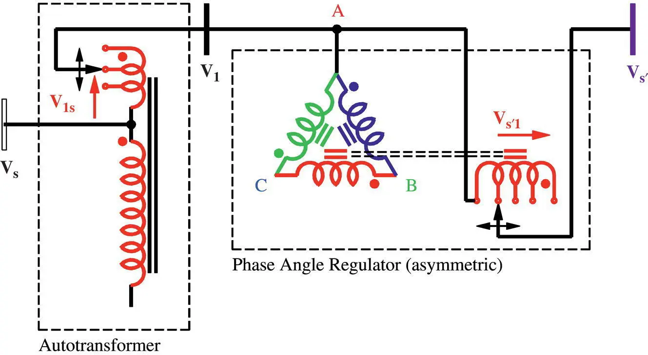
Figure 1-32 Autotransformer/PAR (asym).
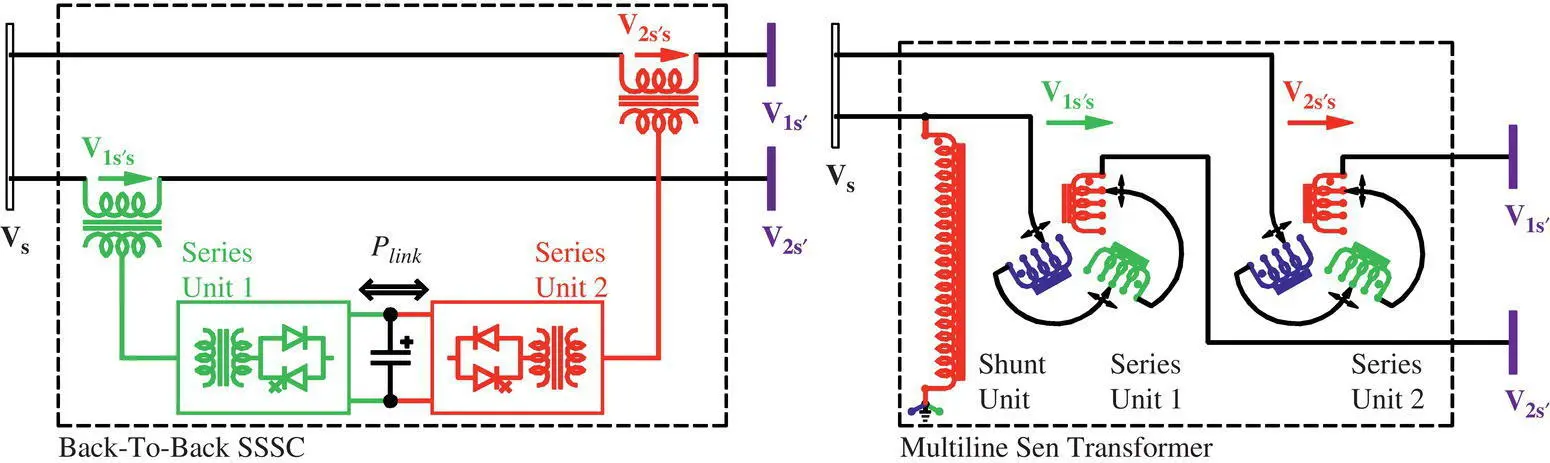
Figure 1-33 Multiline power flow concepts.
The common DC‐link concept can be extended for power exchange between transmission lines with series–series‐connected VSCs. The BTB‐SSSC, also called interline power flow controller (IPFC), shown in Figure 1-33, consists of at least two VSCs; each VSC is connected in series with a transmission line. All the VSCs are connected at their common DC link. The BTB‐SSSC transfers active power from one or more transmission lines, referred to as “leader” lines, to the others, referred to as “follower” lines, and provides an independent series reactive power compensation in each line. A BTB‐SSSC selectively controls the active and reactive power flows in each line in a multiline transmission system and provides a power flow management for the transmission system by decreasing the power flow in an overloaded line and increasing the power flow in an underloaded line. The Multiline Sen Transformer, shown in Figure 1-33, provides the same functionality.
In summary, mechanically or electronically switched compensators are used as PFCs, but each of these compensators can control only one of the three power flow control parameters: line voltage magnitude, its phase angle, and line reactance. Although the active power flow in the line is regulated, the undesirable reactive power flow is also affected simultaneously, but the optimization of power flow that generates the most revenue can be achieved through independent control of active and reactive power flows in the transmission line. Therefore, the power industry’s present need requires the use of PFCs that can independently control both active and reactive power flows in a transmission line, decrease the power flow in an overloaded line, and increase it in an underloaded line, while at the same time keeping the system voltage within the allowable upper and lower limits. The summary of choices for transmission line power flow control equipment is shown in Figure 1-34in chronological order of their introduction in the industry.
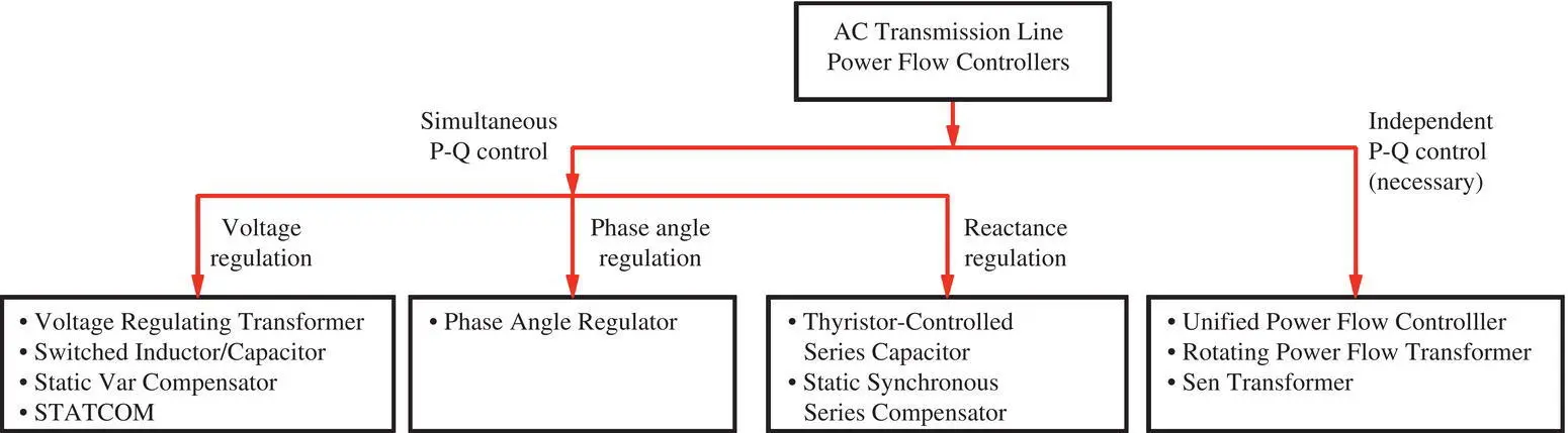
Figure 1-34 Choices for transmission line control equipment.
Table 1-2 Various features of all Shunt–Shunt and Shunt–Series configurations.
| Features | VSC | EM | Transformer/LTCs |
|---|---|---|---|
| Shunt–Shunt configuration | |||
| Independent P‐Q flow control | Yes | Yes | Yes |
| Different frequency system | Yes | Yes | No |
| Different phase angle system | Yes | Yes | Yes |
| Intermediate DC transmission | Yes | No | No |
| Shunt–Series configuration | |||
| Independent P‐Q flow control | Yes | Yes | Yes |
| One frequency system | Yes | Yes | Yes |
| Cost | High | Medium | Low |
The various features of all Shunt–Shunt and Shunt–Series configurations are summarized in Table 1-2. The VSC‐based solutions provide more features than the electrical machine (EM)‐based solutions, which provide more features than the transformer/LTC‐based solutions. However, most of the power flow control needs are in synchronous networks and the use of the Shunt–Series configuration of the ST that uses transformer/LTC‐based solutions is sufficient to meet the utilities’ power flow control needs in the most cost‐effective way.
It is shown in Chapter 3, Section 3.4 that the active and reactive power flow control area is virtually the same for the ST and UPFC. While the UPFC is a FACTS Controller that uses power electronics‐based VSC, the ST, in its preferred form, uses only transformers and LTCs. The reference, titled “Comparison of the ‘Sen’ Transformer with the Unified Power Flow Controller,” IEEE Trans. on Power Delivery , vol. 18, no. 4, pp. 1523−1533, Oct. 2003, states that “At the present time, two major drawbacks of all VSC‐based FACTS Controllers are their high installation and operating costs.” Over the decades, the list of drawbacks has expanded to include component obsolescence, impracticability of relocation, and lack of interoperability. Since the commissioning of the first commercial VSC‐based FACTS Controller more than two decades ago, a great deal has been learned about the true needs of a utility for its everyday use and they are
high reliability, requiring the lowest number of components
low installation and operating costs
component non‐obsolescence
interoperability (components usage from various suppliers), and
easy relocation to adapt to changing power system’s needs
while providing an independent control of active and reactive power flows. In response to these requirements, the novel impedance regulation method of a UPFC and the proven and reliable transformer/LTC technology that is used in a PAR for almost a century are combined to create the ST. This low‐cost form of an IR can improve the fault level in otherwise weak networks, thereby making it possible to have a widely connected grid‐scale renewable generation in weaker and isolated parts of the transmission networks as outlined in PES‐TR‐77, titled “Stability Definitions and Characterization of Dynamic Behavior in Systems with High Penetration of Power Electronic Interfaced Technologies,” which is available at https://resourcecenter.ieee‐pes.org/technical‐publications/technical‐reports/PES_TP_TR77_PSDP_stability_051320.html .
1.6 SMART Power Flow Controller (SPFC)
Today’s power grid, shown in Figure 1-35, has integrated 100s of MW‐range renewable generation. The primary driving factor for integrating more clean, renewable energy sources to the grid is the desire to reduce the use of carbon‐based generation, which will lower GHG emissions. However, a typical characteristic of renewable energy, i.e . solar photovoltaic and offshore or land‐based wind, is the intermittent nature and the resulting unsteady power flow to the load centers. To avoid resulting brown‐outs and/or black‐outs from this intermittency, the power flow in a transmission line needs to be controlled by using a SMART PFC (SPFC) that provides the needed dynamic response. So, traditional steady‐state PFCs, such as series‐connected reactor and capacitor need to be updated with an improved dynamic response. Additionally, there is an increased need for a bidirectional power flow when the renewable generation is unavailable.
Читать дальшеИнтервал:
Закладка:
Похожие книги на «Power Flow Control Solutions for a Modern Grid Using SMART Power Flow Controllers»
Представляем Вашему вниманию похожие книги на «Power Flow Control Solutions for a Modern Grid Using SMART Power Flow Controllers» списком для выбора. Мы отобрали схожую по названию и смыслу литературу в надежде предоставить читателям больше вариантов отыскать новые, интересные, ещё непрочитанные произведения.


Обсуждение, отзывы о книге «Power Flow Control Solutions for a Modern Grid Using SMART Power Flow Controllers» и просто собственные мнения читателей. Оставьте ваши комментарии, напишите, что Вы думаете о произведении, его смысле или главных героях. Укажите что конкретно понравилось, а что нет, и почему Вы так считаете.