Kalyan K. Sen - Power Flow Control Solutions for a Modern Grid Using SMART Power Flow Controllers
Здесь есть возможность читать онлайн «Kalyan K. Sen - Power Flow Control Solutions for a Modern Grid Using SMART Power Flow Controllers» — ознакомительный отрывок электронной книги совершенно бесплатно, а после прочтения отрывка купить полную версию. В некоторых случаях можно слушать аудио, скачать через торрент в формате fb2 и присутствует краткое содержание. Жанр: unrecognised, на английском языке. Описание произведения, (предисловие) а так же отзывы посетителей доступны на портале библиотеки ЛибКат.
- Название:Power Flow Control Solutions for a Modern Grid Using SMART Power Flow Controllers
- Автор:
- Жанр:
- Год:неизвестен
- ISBN:нет данных
- Рейтинг книги:5 / 5. Голосов: 1
-
Избранное:Добавить в избранное
- Отзывы:
-
Ваша оценка:
Power Flow Control Solutions for a Modern Grid Using SMART Power Flow Controllers: краткое содержание, описание и аннотация
Предлагаем к чтению аннотацию, описание, краткое содержание или предисловие (зависит от того, что написал сам автор книги «Power Flow Control Solutions for a Modern Grid Using SMART Power Flow Controllers»). Если вы не нашли необходимую информацию о книге — напишите в комментариях, мы постараемся отыскать её.
Power Flow Control Solutions for a Modern Grid using SMART Power Flow Controllers
Power Flow Control Solutions for a Modern Grid using SMART Power Flow Controllers
Power Flow Control Solutions for a Modern Grid Using SMART Power Flow Controllers — читать онлайн ознакомительный отрывок
Ниже представлен текст книги, разбитый по страницам. Система сохранения места последней прочитанной страницы, позволяет с удобством читать онлайн бесплатно книгу «Power Flow Control Solutions for a Modern Grid Using SMART Power Flow Controllers», без необходимости каждый раз заново искать на чём Вы остановились. Поставьте закладку, и сможете в любой момент перейти на страницу, на которой закончили чтение.
Интервал:
Закладка:
Table 1-1 Economic Analysis of ST versus UPFC over a 45‐year time period.
| Compensators | UPFC | ST |
|---|---|---|
| Base Equipment size | 100 MVA | 100 MVA |
| Life | 15 years | 45 years |
| Equipment First Cost | $50 M | $10 M |
| Project First Cost | $100 M | $20 M |
| Annual Operation & Maintenance (O&M) Costs | $X | $0.1 X |
| Discount Rate | 10% | 10% |
| Equivalent Present project Cost over 45‐year life | $129.66 M | $20 M |
| Equivalent Present Project Cost over 45‐year life ratio | 6.483 | 1 |
| Equivalent Annual Cost over 45‐year life | $13.147 M | $2.0278 M |
| Equivalent Annual Cost over 45‐year life ratio | 6.483 | 1 |
| Annual Savings of ST over UPFC | $11.1192M | |
| Present Value of Savings of ST over UPFC | $109.66 M |
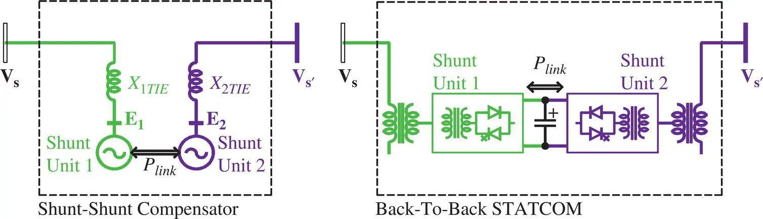
Figure 1-26 Point‐to‐point transfer of power with local reactive power compensation using a Shunt–Shunt Compensator‐based BTB‐STATCOM.
Assuming that the sending‐end voltage ( V s= V s∠ δ s), receiving‐end voltage ( V r= V r∠ δ r), and the line reactance ( X ) remain unchanged, the compensated active and reactive power flows ( P rand Q r) at the receiving end are
(2‐74) 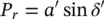
and
(2‐75) 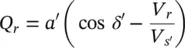
where the magnitude of the voltage ( V s′) at the modified sending end is V s′and the corresponding phase angle is δ s′,
(2‐61) 
and the modified power angle is given by
(2‐62) 
Combining Equations (2-74)and (2-75)and using Equation (2-61), it can be found that for given active and reactive power flows ( P rand Q r) at the receiving end, a PFC with a Shunt–Shunt configuration applies a voltage 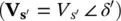 at the modified sending end, such that
(2‐81) 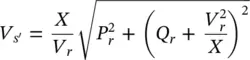
and
(2‐82a) 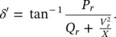
Therefore, a simultaneous regulation of the magnitude ( V s′) and the modified power angle ( δ′ ) of the line voltage is needed for an independent control of active and reactive power flows in the line.
The transfer of power flow from one line to another can be achieved with the use of a BTB‐STATCOM that consists of at least two VSCs, each of which is connected in shunt (parallel) with the transmission line through a coupling transformer. All the VSCs are connected at their common DC link. The shunt‐compensating voltage is of variable magnitude and phase angle, and it is also at any phase angle with the prevailing line current. Accordingly, it exchanges active and reactive powers with the line. The exchanged active power by one VSC flows bidirectionally through the common DC link to another VSC. Each shunt‐connected VSC can also provide an independent shunt reactive power compensation at its AC terminal and, thereby, regulates the voltage at the POC. Each shunt‐connected VSC is rated for the full line voltage and carries the full line current and, therefore, is rated for its full transmitted power. As an example, in order to increase the power flow in a line from its natural flow of 800 MVA to 1000 MVA, the rating of each of the two units of the Shunt–Shunt Compensator would be 1000 MVA. In some special cases for point‐to‐point transfer of power between two isolated networks with different voltages, phase angles, or frequencies, the use of the Shunt–Shunt Compensator may be the preferred solution.
The Shunt–Shunt Compensator may also be implemented, using a common electromechanical or magnetic link in which case, the compensating voltage is generated from either an electrical machine or a transformer with LTCs. In the case of a magnetic link, both active and reactive powers flow through the link. The point‐to‐point transfer of power from one line to another with different voltages, phase angles, or frequencies can be accomplished with the use of shunt–shunt‐connected electrical machines. The Sen Transformer can also generate a shunt‐compensating voltage for the interconnection of two nearby grids with different voltages and phase angles, but the frequencies of the two grids must be the same.
The Shunt–Shunt Compensator is capable of controlling the modified power angle (the phase angle between the modified sending‐end voltage and the receiving‐end voltage of the transmission line) in the range of 0 °≤ δ′ ≤ 360 °. The range of maximum transfer of power along a lossless transmission line (with a quality factor Q = X / R = ∞) between the modified sending and receiving ends takes place at δ ′ = 90° as shown in Figure 1-27. At the same time, the actual δ′ is significantly lower and depends on the line length, system characteristics, and load flows. A transmission line with the natural (uncompensated) power angle ( δ ) in the range of 15 to 20 °may have a possible range of compensation of an additional 5 to 10 °as discussed in Chapter 2, Section 2.2.2. As an example, using a series‐compensating voltage of 0.2 pu, a compensation range ( ψ max) of ±11.54° with an uncompensated power angle ( δ ) of 30° is shown in the shaded area in Figure 1-27. Therefore, the Shunt–Shunt Compensator is severely restricted to operate within the first quadrant when used as a PFC. Then the question arises: “Is it possible to design a new PFC that can control the same amount of transmitted power that is controlled by the Shunt–Shunt Compensator and operate within the allowable range of power angles, while the power rating of this new PFC is a fraction of the conventional Shunt–Shunt Compensator?” For the same example of increasing the power flow in the line from its natural flow of 800 MVA to 1000 MVA, the rating of each of the two units of the Shunt–Series Compensator might be only 200 MVA, resulting in a saving of 80% of the power rating, compared to a Shunt–Shunt Compensator.
Читать дальшеИнтервал:
Закладка:
Похожие книги на «Power Flow Control Solutions for a Modern Grid Using SMART Power Flow Controllers»
Представляем Вашему вниманию похожие книги на «Power Flow Control Solutions for a Modern Grid Using SMART Power Flow Controllers» списком для выбора. Мы отобрали схожую по названию и смыслу литературу в надежде предоставить читателям больше вариантов отыскать новые, интересные, ещё непрочитанные произведения.


Обсуждение, отзывы о книге «Power Flow Control Solutions for a Modern Grid Using SMART Power Flow Controllers» и просто собственные мнения читателей. Оставьте ваши комментарии, напишите, что Вы думаете о произведении, его смысле или главных героях. Укажите что конкретно понравилось, а что нет, и почему Вы так считаете.