Kalyan K. Sen - Power Flow Control Solutions for a Modern Grid Using SMART Power Flow Controllers
Здесь есть возможность читать онлайн «Kalyan K. Sen - Power Flow Control Solutions for a Modern Grid Using SMART Power Flow Controllers» — ознакомительный отрывок электронной книги совершенно бесплатно, а после прочтения отрывка купить полную версию. В некоторых случаях можно слушать аудио, скачать через торрент в формате fb2 и присутствует краткое содержание. Жанр: unrecognised, на английском языке. Описание произведения, (предисловие) а так же отзывы посетителей доступны на портале библиотеки ЛибКат.
- Название:Power Flow Control Solutions for a Modern Grid Using SMART Power Flow Controllers
- Автор:
- Жанр:
- Год:неизвестен
- ISBN:нет данных
- Рейтинг книги:5 / 5. Голосов: 1
-
Избранное:Добавить в избранное
- Отзывы:
-
Ваша оценка:
Power Flow Control Solutions for a Modern Grid Using SMART Power Flow Controllers: краткое содержание, описание и аннотация
Предлагаем к чтению аннотацию, описание, краткое содержание или предисловие (зависит от того, что написал сам автор книги «Power Flow Control Solutions for a Modern Grid Using SMART Power Flow Controllers»). Если вы не нашли необходимую информацию о книге — напишите в комментариях, мы постараемся отыскать её.
Power Flow Control Solutions for a Modern Grid using SMART Power Flow Controllers
Power Flow Control Solutions for a Modern Grid using SMART Power Flow Controllers
Power Flow Control Solutions for a Modern Grid Using SMART Power Flow Controllers — читать онлайн ознакомительный отрывок
Ниже представлен текст книги, разбитый по страницам. Система сохранения места последней прочитанной страницы, позволяет с удобством читать онлайн бесплатно книгу «Power Flow Control Solutions for a Modern Grid Using SMART Power Flow Controllers», без необходимости каждый раз заново искать на чём Вы остановились. Поставьте закладку, и сможете в любой момент перейти на страницу, на которой закончили чтение.
Интервал:
Закладка:
This book is accompanied by a companion website:
www.wiley.com/go/sen/powerflowcontrol
All EMTP models that are discussed throughout the book are available in the companion website.
1 Smart Controllers
The future transmission and distribution system is on the way to be dramatically different from what it is today. Today’s Bulk Power System (BPS), referred to as grid, that encompasses mainly electromechanical devices is continuously integrating Inverter‐Based Resources (IBRs) to convert renewable energy sources into electricity. However, most of these sources are solar and wind, which are intermittent in nature. Commercial nuclear‐powered generators, once turned on, deliver electric power continuously for the next 18 to 24 months before stopping for scheduled maintenance and refueling. This difference alone, in two different types of electricity generation, creates a need for a SMART controller that is capable of managing power flow dynamically. A SMART controller will be essential to increase the transmission capacity of the existing system with line impedance management and the needed dynamic performance. This technology will help operators optimize power flows across the grid to reduce voltage stress on the transmission network, reduce line loss, as well as reduce Green‐House Gas (GHG) emissions from traditional carbon‐based generation.
SMART is an acronym that stands for Specific, Measurable, Attainable, Relevant, and Time‐bound. SMART solutions, which have been used for decades in many fields, are well suited for applications in electrical engineering. A controller, also referred to as a compensator, is a general term to describe a regulator that regulates voltage, current, phase angle of a line voltage, resistance, reactance, impedance, and so on, directly or indirectly in an electric circuit. A controller can be designed to perform a task ( e.g . voltage regulation) and/or multiple tasks with varying cost and complexity. In the simplest term, a SMART Controller is what one procures is based on what one needs. A SMART Controller is an evolving technology that uses the best technical features from all previous concepts to meet the present need by blending functional requirements with the most cost‐effective solution. A SMART Power Flow Controller (SPFC) enhances the power flow controllability in electric power transmission and distribution systems. It is recommended that utilities choose a solution that meets their need in terms of reliability, robustness, cost‐effectiveness, component non‐obsolescence, efficiency, ease of relocation, and interoperability.
1.1 Why is a Power Flow Controller Needed?
The electricity generation is typically located a distance away from the industrial and population, i.e . load centers. Therefore, electricity is transmitted from the points of generation to the points of utilization using transmission and distribution lines. One of the major achievements of the late 19th century was to implement long‐distance alternating current (AC) transmission of electric power. For a given amount of transmitted power, a higher transmission voltage provides less footprint and less current in the line. Since loss in the line is proportional to the square of the current, it is most desirable to transmit electricity from generation to load centers through the transmission lines at higher voltage and lower current. Over the next century, various types of generation, such as coal, natural gas, nuclear, hydro, renewables, and so on, and loads were integrated through interconnected transmission and distribution lines to form the grid as shown in Figure 1-1.
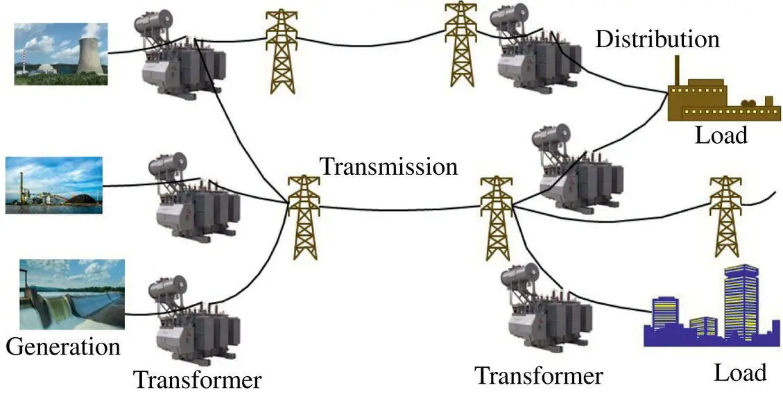
Figure 1-1 Part of a large interconnected transmission system supplying electric power from the generating point to the loads.
Electricity flows freely from a higher potential to a lower potential. If two or more lines with different impedances are connected in parallel, the current in each line is, in some form, inversely proportional to the respective line impedance. This free flow of electricity might take longer paths to reach its destination and cause unwanted power losses in the lines. Additionally, this free flow may cause some transmission lines to be overloaded or underloaded. If the impedance of a line is larger compared to that of the lines connected in parallel, the current and the resulting power flow through the higher‐impedance line is lower compared to that in the neighboring lines, and vice versa. Therefore, power flow in a line is, in some form, inversely proportional to the impedance of the line.
Transmission Reliability Margin (TRM) – the amount of Transmission Transfer Capability (TTC) needed to ensure that the interconnected transmission network is secure under a reasonable range of uncertainties in system conditions. These uncertainties may result from the following:
1 Simultaneous limitations with a parallel path.
2 Reservations for unscheduled flow, i.e. loop flow.
3 Reservations for unplanned transmission outages, i.e. for paths in which contingencies have not already been included in the calculation of TTC.
TRM does not include reservations for planned outages and other known transmission conditions, which have been included in the calculation of TTC (Minimum of {Thermal Limit, Voltage Limit, and Stability Limit}).
Capacity Benefit Margin (CBM) – the amount of TTC reserved by the load‐serving entities to ensure access to generation from interconnected systems to meet generation reliability requirements. These reservations may include the following:
1 Transmission reserved by the Control Area Operator to accommodate operating reserves (spinning and supplemental). Such operating reserves may not exceed NERC and WECC applicable pool requirements or individual members’ reliability requirements.
2 Transmission reserved for the import of ancillary services (such as spinning reserves) from another control area.
3 Transmission reserved for generation patterns and generation contingencies. These patterns and contingencies must be based upon reasonable, publicly available assumptions subject to evaluation in applicable dispute resolution proceedings.
According to “Available Transfer Capability Definitions and Determination,” North American Electric Reliability Council, June 1996, TTC is defined as
(1‐1) 
Available Transfer Capability (ATC) is a measure of the transfer capability remaining in the physical transmission network for further commercial activity over and above already committed uses. Therefore,
(1‐2) 
It is often desirable to utilize the ATC to increase the power flow through a line as much as possible according to Equation (1-2), which results in a higher line utilization, meets greater customer needs, integrates new sources of energy, and avoids or defers building of new transmission lines, at least in the short term. Sometimes, it is the opposite when it may be desirable to lower the power flow of the line so that the power flow can be redirected to a desired transmission line that may include high‐voltage and low‐current and thus, low‐loss lines. This is particularly important when a line becomes overloaded with a level of current that can trip the line or a fault current that must be limited. If an overloaded line trips, its current will be redirected in the available lines inversely proportional, depending on the lines’ impedances. This may cause a previously underloaded line to become overloaded and tripped, which may create a possible cascaded failure of the grid, resulting in a blackout. This type of cascaded failure is described in the “Final Report on the August 14, 2003 Blackout in the United States and Canada: Causes and Recommendations” by U.S.‐Canada Power System Outage Task Force, April 2004.
Читать дальшеИнтервал:
Закладка:
Похожие книги на «Power Flow Control Solutions for a Modern Grid Using SMART Power Flow Controllers»
Представляем Вашему вниманию похожие книги на «Power Flow Control Solutions for a Modern Grid Using SMART Power Flow Controllers» списком для выбора. Мы отобрали схожую по названию и смыслу литературу в надежде предоставить читателям больше вариантов отыскать новые, интересные, ещё непрочитанные произведения.


Обсуждение, отзывы о книге «Power Flow Control Solutions for a Modern Grid Using SMART Power Flow Controllers» и просто собственные мнения читателей. Оставьте ваши комментарии, напишите, что Вы думаете о произведении, его смысле или главных героях. Укажите что конкретно понравилось, а что нет, и почему Вы так считаете.