Flexible Thermoelectric Polymers and Systems
Здесь есть возможность читать онлайн «Flexible Thermoelectric Polymers and Systems» — ознакомительный отрывок электронной книги совершенно бесплатно, а после прочтения отрывка купить полную версию. В некоторых случаях можно слушать аудио, скачать через торрент в формате fb2 и присутствует краткое содержание. Жанр: unrecognised, на английском языке. Описание произведения, (предисловие) а так же отзывы посетителей доступны на портале библиотеки ЛибКат.
- Название:Flexible Thermoelectric Polymers and Systems
- Автор:
- Жанр:
- Год:неизвестен
- ISBN:нет данных
- Рейтинг книги:3 / 5. Голосов: 1
-
Избранное:Добавить в избранное
- Отзывы:
-
Ваша оценка:
Flexible Thermoelectric Polymers and Systems: краткое содержание, описание и аннотация
Предлагаем к чтению аннотацию, описание, краткое содержание или предисловие (зависит от того, что написал сам автор книги «Flexible Thermoelectric Polymers and Systems»). Если вы не нашли необходимую информацию о книге — напишите в комментариях, мы постараемся отыскать её.
Comprehensive review of the rapidly evolving field of flexible thermoelectric polymers Flexible Thermoelectric Polymers and Systems
Flexible Thermoelectric Polymers and Systems
Flexible Thermoelectric Polymers and Systems — читать онлайн ознакомительный отрывок
Ниже представлен текст книги, разбитый по страницам. Система сохранения места последней прочитанной страницы, позволяет с удобством читать онлайн бесплатно книгу «Flexible Thermoelectric Polymers and Systems», без необходимости каждый раз заново искать на чём Вы остановились. Поставьте закладку, и сможете в любой момент перейти на страницу, на которой закончили чтение.
Интервал:
Закладка:
where n (e) and μ ( E ) are the charge carrier density and mobility at energy E . Hence, a semiconductor with a large variation in the carrier density near the Fermi level can have a high Seebeck coefficient. This can be achieved by changing the band structure. This way to increase the Seebeck coefficient is called “band structure engineering”. In addition, the charge carrier density n ( E ) is related to the density of states (DOS), g ( E ),
(1.8) 
Thus, the Seebeck coefficient is related to the density of states near E F. Controlling the density of states can vary the Seebeck coefficient, and this is called “DOS engineering”.
Another important formula is the dependence of the Seebeck coefficient on the difference between the average energy ( E J) of the transporting electrons and the E F,
(1.9) 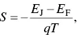
where q is the elementary charge. A simple picture of an n ‐type semiconductor is shown in Figure 1.4. The charge carriers are the electrons in the conduction band. Their average energy is E J. For n ‐type semiconductors, E J− E F> 0, the Seebeck coefficient is negative. In contrast, E J− E F< 0 for p ‐type semiconductors, the Seebeck coefficient is positive. When the | E J− E F| value is large, the material will have a high Seebeck coefficient. Increasing the doping level of an n ‐type semiconductor can shift the Fermi level upward to the conduction band and thus lower the | E J− E F| value. Similar argument can be applied for p ‐type semiconductors. Hence, the Seebeck coefficient decreases with the increase in the doping level.
Although increasing the doping level can decrease the Seebeck coefficient, it increases the electrical conductivity. The power factor ( S 2 σ ) is dependent on the Seebeck coefficient and the electrical conductivity ( σ ). As shown in Figure 1.5, there is an optimal power factor in terms of the charge carrier density.
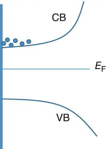
Figure 1.4 Band structure of an n ‐type semiconductor. VB and CB are for the valence band and conduction band, respectively. The dots at the CB stand for electrons.
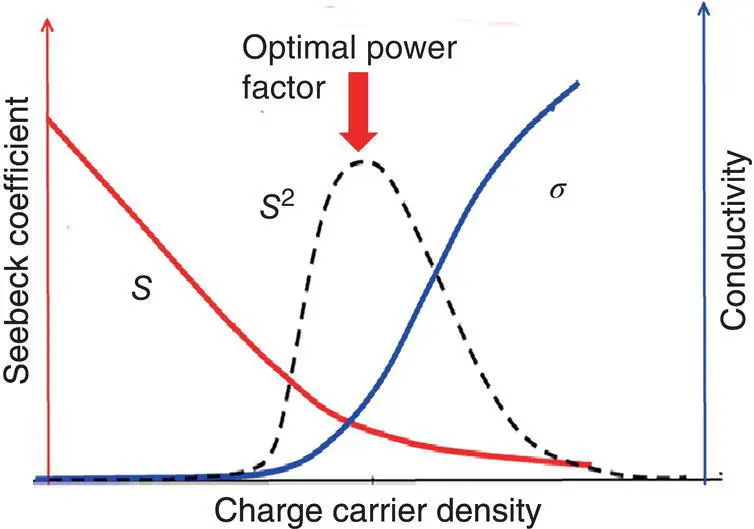
Figure 1.5 Dependence of the Seebeck coefficient, electrical conductivity, and power factor on the charge carrier concentration.
The dependence of the power factor on the charge carrier density is valid for conducting polymers as well. The Seebeck coefficient and electrical conductivity of conducting polymers strongly depend on the doping level. An undoped conducting polymer has a conductivity in the insulator range. The increase in the doping level can decrease the Seebeck coefficient while increase the electrical conductivity. Thus, doping engineering is an effective way to find the optimal power factor of conducting polymers as well. Chemical and electrochemical de‐dopings are popular methods to find the optimal doping level of conducting polymers in terms of the power factor. For example, Crispin et al. chemically de‐doped PEDOT:TsO with tetrakis(dimethylamino)ethylene (TDAE) and found the optimal doping level of ~0.22 ( Figure 1.6) [5].
The Seebeck coefficient of conducting polymers is also related to the doping form. There are two types of doping forms for p ‐type conducting polymers [6, 7]. Taking away electrons from the conjugated backbone is the oxidative doping. Oxidative doping is the main doping form for conjugated polymers such as polyacetylene and polythiophene. The oxidative doping can be de‐doped by reducing chemical agents. Another doping form is the protonic acid doping. It is the main doping form for polyaniline because polyaniline has ammine group [8]. Protonic acid doping was observed for polypyrrole and polythiophene as well [6, 7]. The protonic acid doping can be de‐doped by base. Yao et al. found that de‐doping the protonic acid doping by base is more effective in increasing the Seebeck coefficient than de‐doping the oxidative doping [3]. As shown in Figure 1.7, poly(3,4‐ethylenedioxythiophene):trifluoromethanesulfonate (PEDOT:OTf) can be de‐doped with reducing agents including glucose and ascorbic acid or NaOH. When PEDOT:PSS:OTf is de‐doped to the same doping level, the conductivity using glucose or ascorbic acid is similar with NaOH. But the latter can give rise to a higher Seebeck coefficient and thus the power factor than the former. This difference is ascribed to the different electronic structures by oxidative doping and protonic acid doping. The protonic acid doping takes place by attaching a proton to an α or β site of the thiophene ring of PEDOT. This distorts the conjugated structure and leads to more electrons near the Fermi level. Instead, the oxidative doping does not affect the conjugated structure. Thus, the removal of the protonic acid doping can more effectively increase the mean energy ( E J) of the charge carriers and thus increase the Seebeck coefficient more remarkably.
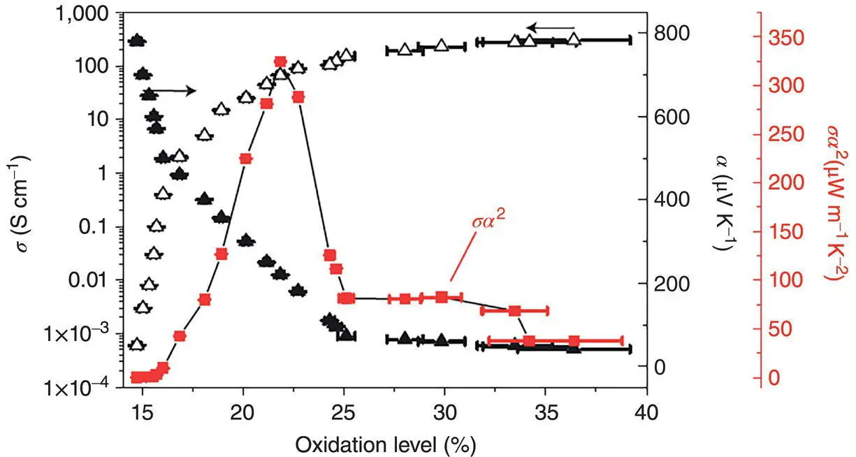
Figure 1.6 Dependences of the electrical conductivity, Seebeck coefficient, and power factor of PEDOT:Tso on the doping level. Oxidation level is used for the doping level, and α is used for the Seebeck coefficient.
Source: Bubnova et al. [5]. © Springer Nature.
The dependence of the Seebeck coefficient on the | E J− E F| values is often used to understand the energy filtering. Energy filtering is often observed when an electronic material like nano‐fillers is mixed into a conducting polymer with different Fermi levels [9–11]. The different Fermi levels of the matrix and nano‐fillers can induce the charge transfer and an internal electric field at the interface between them. This internal electric field at the interface can block the accumulation of the charge carriers with low energy and thus increase the mean energy ( E J) of the accumulated charge carriers under temperature gradient. Apart from composites of conducting polymers, energy filtering was reported when a certain material is coated on a conducting polymer film [12–14].
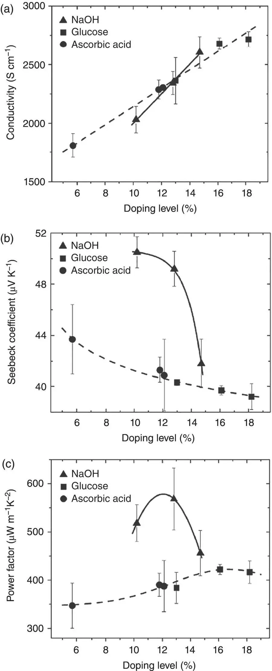
Figure 1.7 (a) Conductivity, (b) Seebeck coefficient, and (c) power factor of PEDOT:OTf films as a function of doping levels. NaOH, glucose, and ascorbic acid were used to de‐dope PEDOT:OTf.
Source: Yao et al. [7]. © Royal Society of Chemistry.
1.1.3 Peltier Effect
Electrical current is generated at the presence of temperature gradient in terms of the Seebeck effect. There is a reverse process to take away heat by applying an electrical current to a thermoelectric material. This is called the Peltier effect. When a charge carrier transports from the cold side to the hot side, it will bring heat from the cold side to the hot side. Thus, this can lower the temperature of the cold side.
Читать дальшеИнтервал:
Закладка:
Похожие книги на «Flexible Thermoelectric Polymers and Systems»
Представляем Вашему вниманию похожие книги на «Flexible Thermoelectric Polymers and Systems» списком для выбора. Мы отобрали схожую по названию и смыслу литературу в надежде предоставить читателям больше вариантов отыскать новые, интересные, ещё непрочитанные произведения.


Обсуждение, отзывы о книге «Flexible Thermoelectric Polymers and Systems» и просто собственные мнения читателей. Оставьте ваши комментарии, напишите, что Вы думаете о произведении, его смысле или главных героях. Укажите что конкретно понравилось, а что нет, и почему Вы так считаете.