John III Beumer - Fundamentals of Implant Dentistry
Здесь есть возможность читать онлайн «John III Beumer - Fundamentals of Implant Dentistry» — ознакомительный отрывок электронной книги совершенно бесплатно, а после прочтения отрывка купить полную версию. В некоторых случаях можно слушать аудио, скачать через торрент в формате fb2 и присутствует краткое содержание. Жанр: unrecognised, на английском языке. Описание произведения, (предисловие) а так же отзывы посетителей доступны на портале библиотеки ЛибКат.
- Название:Fundamentals of Implant Dentistry
- Автор:
- Жанр:
- Год:неизвестен
- ISBN:нет данных
- Рейтинг книги:5 / 5. Голосов: 1
-
Избранное:Добавить в избранное
- Отзывы:
-
Ваша оценка:
Fundamentals of Implant Dentistry: краткое содержание, описание и аннотация
Предлагаем к чтению аннотацию, описание, краткое содержание или предисловие (зависит от того, что написал сам автор книги «Fundamentals of Implant Dentistry»). Если вы не нашли необходимую информацию о книге — напишите в комментариях, мы постараемся отыскать её.
Fundamentals of Implant Dentistry — читать онлайн ознакомительный отрывок
Ниже представлен текст книги, разбитый по страницам. Система сохранения места последней прочитанной страницы, позволяет с удобством читать онлайн бесплатно книгу «Fundamentals of Implant Dentistry», без необходимости каждый раз заново искать на чём Вы остановились. Поставьте закладку, и сможете в любой момент перейти на страницу, на которой закончили чтение.
Интервал:
Закладка:
To overcome the biomechanical limitations of implant prostheses, special occlusal considerations have been proposed in the literature for reducing the likelihood of implant overloading. 8, 10, 12, 13These considerations are centered on increasing the proportion of axial forces and reducing the proportion of nonaxial forces. This involves the number of implants, orientation of the implants, prosthesis design, and application of protective devices. 12To ensure that the implants and the surrounding bone are not overloaded, a sufficient number of well-distributed implants should be placed to support the prosthesis. The implants should be placed in a way that will allow loading in a direction that is parallel to the implant. The occlusion for the prosthesis should be designed for the purpose of reducing lateral forces applied to the implant. The occlusal design is largely dependent on the prosthesis design and location as well as the condition of the adjacent teeth and opposing dentition. In general, the occlusal design should be optimized by reducing prosthesis cantilever, reducing cuspal inclination, and narrowing the occlusal table. 12, 14– 17Heavy maximal intercuspation and lateral occlusal contacts can be further controlled by splinting multiple implants and reducing the lateral contacts on the implant prosthesis by relying on the remaining natural dentition. In addition, the damaging effect of heavy occlusal forces can be controlled by providing an occlusal splint.
Biomechanics of prosthesis design
If occlusal design and muscles of mastication dictate the magnitude and direction of occlusal forces, then prosthesis design governs how these occlusal forces are transmitted to the underlying abutments, implants, and ultimately, bone.
Individual vs splinted configuration
In a well-osseointegrated implant, the supporting bone resists against translation, and the motion of the implant becomes tipping, bending, and rotation. For example, a premature working-side interference on a posterior implant can result in disclusion of other teeth, reduction of contact surface area (fewer teeth touching), and translation of the load point toward the fulcrum TMJ. All these combine to increase stress that tips, bends, and rotates the implant around its center of mass. Even with the most ideally designed prostheses, normal mastication and routine function can produce nonaxial stresses and can result in moments. The design goal is to minimize—not eliminate—nonaxial stresses. In practice, time-tested procedures such as clinical remounts will reduce stress concentration and overall nonaxial stresses (see later in the chapter).
Splinting can distribute the dynamic loads and strains during function and parafunction more uniformly to the supporting implants, thereby reducing the probability of localized overloading. While some finite element analysis studies show that splinting does not reduce peak strains significantly when there is optimal crown-to-implant ratio, especially when using implants with internal connections, it is critical to understand that although episodic peak loads can be dangerous, greater uniformity reduces the cyclic loads and directly increases the number of fatigue cycles before failure. Furthermore, dentists cannot adequately predict which implants will suffer from future peri-implant bone loss. As bone resorbs around an implant, the center of mass moves apically, increasing the distance between the occlusal table and the center of mass. This ultimately results in greater moments, producing more nonaxial deformation and motion on nonsplinted implants.
Perhaps more important than load distribution, splinting reduces the amount of rotation around the implant axis (yaw), thereby minimizing shear stress on implant-bone interface around the vertical long axis of the implant. A good example that illustrates the significant antirotation effect of splinting is the fact that nonengaging abutments can be used successfully to splint two implants together, but nonengaging features will not resist rotation as single-implant abutments. Compared to single-unit implant restorations, splinting stabilizes the supporting implants by reducing the degree of freedom against implant rotation and mesiodistal tipping. Besides reducing stress on implants and bone, splinting also reduces rotational deformation on abutment screws, incidence of screw failure, and other complications. 18
With the widespread availability of digital planning and milling as well as the ability to achieve passive fit and emergence profile to facilitate oral hygiene, the authors recommend splinting implants in most clinical situations, especially in posterior regions. Systematic review of 36 finite element analyses conclude that splinting may reduce crestal marginal bone loss, especially in short implants. 19Based on clinical experience, splinting is recommended when the applied stresses are high and when the supporting abutments (eg, external hex, rotating ball joints, nonengaging abutments) or implants (eg, short, narrow, compromised bone) may cause excessive stresses that can expedite fatigue failure, wear, plastic deformation, rupture, creep, fretting fatigue, and failure of implant-prosthesis components. The clinical justification for splinting will be detailed further in subsequent chapters (see chapter 11, section entitled “Individual implants versus splinted implant designs”).
For multi-unit prostheses, nonaxial forces at connectors can be countered by shortening the span of the unsupported segment or increasing the cross-sectional area of the connectors to maximize the angular mass or rotational inertia. Otherwise, the pontic connectors are at risk of mechanical failure. For posterior teeth in Class I occlusion, this resistance against vertical forces is dominated by the span length ( L ) and connector apical-occlusal height ( h ) ( Fig 3-3), as deflection is related to the third power of both L and h . For maxillary anterior teeth with Class II occlusion and steep vertical overlap, resistance against horizontal forces is related to the third power of the connector width. The dimensions should not be excessive; they must be optimized for esthetics and allow access for oral hygiene. In many cases, the span length is beyond the control of the prosthodontist or restorative dentist, hence the primary control defaults to connector dimension—more specifically, the dimension that parallels the load axis governs the inertial resistance against deformation (occlusal gingival height for posterior teeth, buccolingual width for anterior teeth).
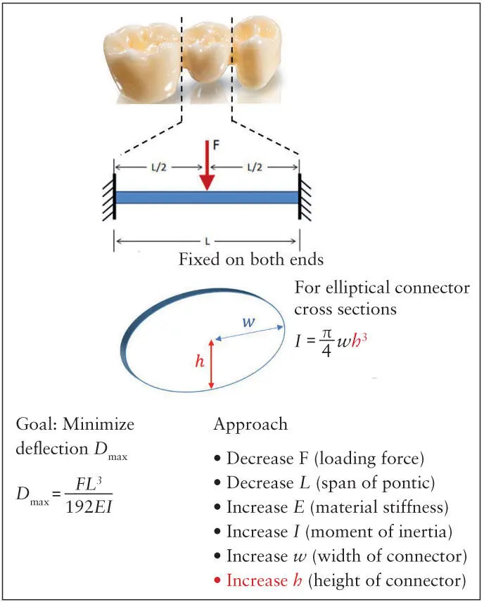
Fig 3-3 Prosthesis design parameters that control bending deformation ( D max), span length ( L ), and connector height ( h ) are the most important for posterior teeth under a vertical loading force ( F ). The moment of inertia for elliptical cross section is shown. Other cross-section geometries seen in dentistry would alter the equation, but the term wh 3remains unchanged.
Linear vs curvilinear configurations
The previous section suggests that antirotation and load uniformity are the primary benefits of splinting. That is certainly true with implants that are splinted linearly, that is, the centroid of all connecting implants are roughly aligned along a straight line (this forms the so-called “centroidal axis”). In the resting, unloaded state, there is no stress or strain anywhere within the prosthesis. When this linear configuration is loaded, stress and strain are distributed throughout the prosthesis except the path of a second axis that runs perpendicular to the load axis throughout the cross section of the prosthesis—the neutral axis , which is defined as the line along which stress and strain (hence “neutral”) are zero when the prosthesis is subjected to linear elastic bending moments. In linear configurations, the centroidal axis and the neutral axis are usually collinear for isotropic, symmetric prosthetic structures prior to visible bending or plastic deformation. Linear configuration is the common design when multiple implants are connected to restore four or fewer teeth.
Читать дальшеИнтервал:
Закладка:
Похожие книги на «Fundamentals of Implant Dentistry»
Представляем Вашему вниманию похожие книги на «Fundamentals of Implant Dentistry» списком для выбора. Мы отобрали схожую по названию и смыслу литературу в надежде предоставить читателям больше вариантов отыскать новые, интересные, ещё непрочитанные произведения.


Обсуждение, отзывы о книге «Fundamentals of Implant Dentistry» и просто собственные мнения читателей. Оставьте ваши комментарии, напишите, что Вы думаете о произведении, его смысле или главных героях. Укажите что конкретно понравилось, а что нет, и почему Вы так считаете.