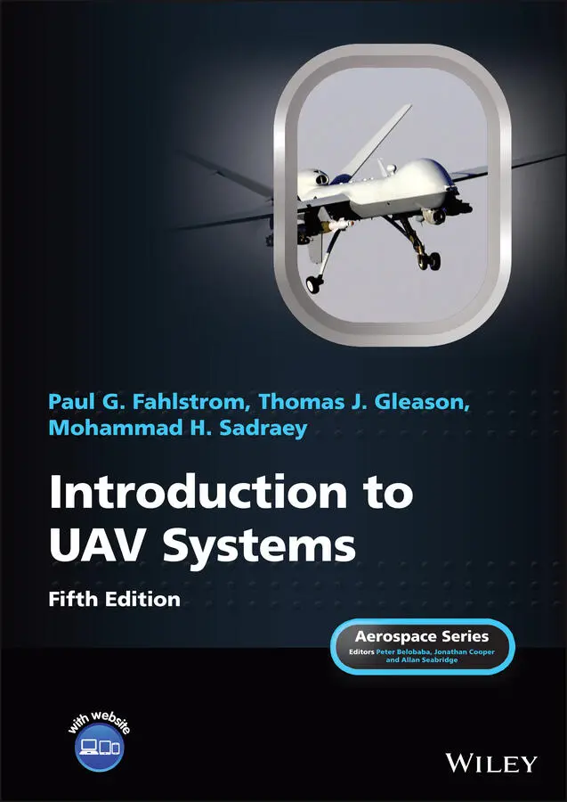
Mohammad H. Sadraey - Introduction to UAV Systems
Здесь есть возможность читать онлайн «Mohammad H. Sadraey - Introduction to UAV Systems» — ознакомительный отрывок электронной книги совершенно бесплатно, а после прочтения отрывка купить полную версию. В некоторых случаях можно слушать аудио, скачать через торрент в формате fb2 и присутствует краткое содержание. Жанр: unrecognised, на английском языке. Описание произведения, (предисловие) а так же отзывы посетителей доступны на портале библиотеки ЛибКат.
- Название:Introduction to UAV Systems
- Автор:
- Жанр:
- Год:неизвестен
- ISBN:нет данных
- Рейтинг книги:5 / 5. Голосов: 1
-
Избранное:Добавить в избранное
- Отзывы:
-
Ваша оценка:
Introduction to UAV Systems: краткое содержание, описание и аннотация
Предлагаем к чтению аннотацию, описание, краткое содержание или предисловие (зависит от того, что написал сам автор книги «Introduction to UAV Systems»). Если вы не нашли необходимую информацию о книге — напишите в комментариях, мы постараемся отыскать её.
The latest edition of the leading resource on unmanned aerial vehicle systems
A thorough introduction to the history of unmanned aerial vehicles, including their use in various conflicts, an overview of critical UAV systems, and the Predator/Reaper A comprehensive exploration of the classes and missions of UAVs, including several examples of UAV systems, like Mini UAVs, UCAVs, and quadcopters Practical discussions of air vehicles, including coverage of topics like aerodynamics, flight performance, stability, and control In-depth examinations of propulsion, loads, structures, mission planning, control systems, and autonomy Introduction to UAV Systems
Design of Unmanned Aerial Systems
Introduction to UAV Systems
Introduction to UAV Systems — читать онлайн ознакомительный отрывок
Ниже представлен текст книги, разбитый по страницам. Система сохранения места последней прочитанной страницы, позволяет с удобством читать онлайн бесплатно книгу «Introduction to UAV Systems», без необходимости каждый раз заново искать на чём Вы остановились. Поставьте закладку, и сможете в любой момент перейти на страницу, на которой закончили чтение.
Интервал:
Закладка:
In 1971, more than a decade before the Israeli success in the Bekaa Valley, the US Army had successfully launched a demonstration UAV program, and had expanded it to include a high‐technology sensor and data link. The sensor and data‐link technology broke new ground in detection, communication, and control capability. The program moved to formal development in 1978 with a 43‐month schedule to produce a production‐ready system. The program was extended to 52 months because the super‐sophisticated MICNS (Modular Integrated Communication and Navigation System) data link experienced troubles and was delayed. Then, for reasons unknown to industry, the Army shut the program down altogether. It was subsequently restarted by Congress (about 1982), but at the cost of extending it to a 70‐month program. From then on everything went downhill.
In 1985, a Red Team formed to review the system came to the conclusion that not only had the system not demonstrated the necessary maturity to continue to production, but also that the systems engineering did not properly account for deficiencies in the integration of the data link, control system, and payload, and it probably would not work anyway. After two more years of intensive effort by the government and contractor, many of the problems were fixed, but nevertheless it failed to demonstrate all of the by then required capabilities during operational testing (OT) II and was never put into production.
The lessons learned in the Aquila program still are important for anyone involved in specifying operational requirement, designing, or integrating a UAS. This book refers to them in the chapters describing reconnaissance and surveillance payloads, and data links in particular, because the system‐level problems of Aquila were largely in the area of understanding those subsystems and how they interacted with each other, with the outside world, and with basic underlying processes such as the control loop that connects the ground controller to the air vehicle and its subsystems.
1.4.1 Aquila Mission and Requirements
The Aquila system was designed to acquire targets and combat information in real time, beyond the line‐of‐sight of supported ground forces. During any single mission, the Aquila was capable of performing airborne target acquisition and location, laser designation for precision‐guided munitions (PGM), target damage assessment, and battlefield reconnaissance (day or night). This is quite an elaborate requirement.
To accomplish this, an Aquila battery needed 95 men, 25 five‐ton trucks, 9 smaller trucks, and a number of trailers and other equipment, requiring several C‐5 sorties for deployment by air. All of this allowed operation and control of 13 air vehicles. The operational concept utilized a central launch and recovery section (CLRS) where launch, recovery, and maintenance were conducted. The air vehicle was flown toward the Forward Line of Own Troops (FLOT), and handed off to a forward control section (FCS), consisting mainly of a ground control station, from which combat operations were conducted.
It was planned that eventually the ground control station with the FCS would be miniaturized and be transported by a High Mobility Multipurpose Wheeled Vehicle (HMMWV) to provide more mobility and to reduce target size when operating close to the FLOT. The Aquila battery belonged to an Army Corps. The CLRS was attached to Division Artillery because the battery supported a division. The FCS was attached to a maneuver brigade.
1.4.2 Air Vehicle
The Aquila air vehicle was a tail‐less flying wing with a rear‐mounted 26‐horsepower, two‐cycle piston engine, and a pusher propeller. Figure 1.3shows the Aquila air vehicle. The fuselage was about 2 m long and the wingspan was 3.9 m. The airframe was constructed of kevlar‐epoxy material but metalized to prevent radar waves from penetrating the skin and reflecting off the square electronic boxes inside. The gross takeoff weight was about 265 lb and it could fly between 90 and 180 km/h up to about 12,000 ft.
1.4.3 Ground Control Station
The Aquila ground control station contained three control and display consoles, video and telemetry instrumentation, a computer and signal processing group, internal/external communications equipment, ground data terminal control equipment, and survivability protection equipment.
The GCS was the command post for the mission commander and had the display and control consoles for the vehicle operator, payload operator, and mission commander. The GCS was powered by a 30‐kW generator. A second 30‐kW generator was provided as a backup. Attached to the GCS by 750 m of fiber‐optic cable was the remote ground terminal (RGT). The RGT consisted of a tracking dish antenna, transmitter, receiver, and other electronics, all trailer‐mounted as a single unit. The RGT received downlink data from the air vehicle in the form of flight status information, payload sensor data, and video. The RGT transmitted both guidance commands and mission payload commands to the air vehicle. The RGT had to maintain line‐of‐sight contact with the air vehicle. It also had to measure the range and azimuth to the air vehicle for navigation purposes, and the overall accuracy of the system depended on the stability of its mounting.
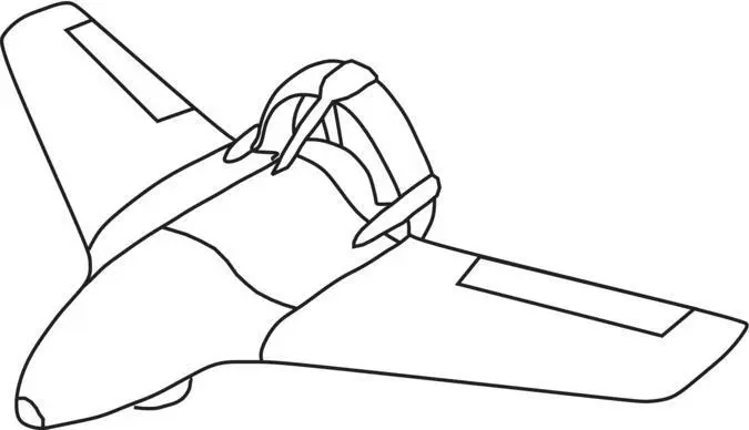
Figure 1.3 Aquila air vehicle
1.4.4 Launch and Recovery
The Aquila launch system contained an initializer that was linked to the RGT and controlled the sequence of the launch procedure including initializing the inertial platform. The catapult was a pneumatic/hydraulic system that launched the air vehicle into the air with the appropriate airspeed.
The air vehicle was recovered in a net barrier mounted on a 5‐ton truck. The net was supported by hydraulic‐driven, foldout arms, which also contained the guidance equipment to automatically guide the air vehicle into the net.
1.4.5 Payload
The Aquila payload was a day video camera (Electro‐Optic) with a bore‐sighted laser rangefinder/designator for designating targets. Once locked on to a target, moving or stationary, it would seldom miss. The laser rangefinder/designator was optically aligned and automatically bore‐sighted with the video camera. Scene and feature track modes provided line‐of‐sight stabilization and auto‐tracking for accurate location and tracking of moving and stationary targets. An infrared (IR) night payload was also under development for use with Aquila.
1.4.6 Other Equipment
An air‐vehicle handling truck was part of the battery ground support equipment and included a lifting crane. The lifting crane was necessary, not because the air vehicle was extremely heavy, but because the box in which it was transported contained lead to resist nuclear radiation. In addition, a maintenance shelter, also on a 5‐ton truck, was used for unit‐level maintenance and was a part of the battery.
1.4.7 Summary
The Aquila system had everything imaginable in what one could call “The Complete UAV System;” “zero‐length” launcher, “zero‐length” automatic recovery with a net, anti‐jam data link, and day and night payload with designator. This came at a very high cost, however – not only in dollars but also in terms of manpower, trucks, and equipment. The complete system became large and unwieldy, which contributed to its downfall. All of this equipment was necessary to meet the elaborate operational and design requirements placed on the Aquila system by the Army, including a level of nuclear blast and radiation survivability (a significant contributor to the size and weight of shelters and the RGT mount). Eventually, it was determined that many of the components of the system could be made smaller and lighter and mounted on HMMWVs instead of 5‐ton trucks, but by that time the whole system had gained a bad reputation for:
Читать дальшеИнтервал:
Закладка:
Похожие книги на «Introduction to UAV Systems»
Представляем Вашему вниманию похожие книги на «Introduction to UAV Systems» списком для выбора. Мы отобрали схожую по названию и смыслу литературу в надежде предоставить читателям больше вариантов отыскать новые, интересные, ещё непрочитанные произведения.


Обсуждение, отзывы о книге «Introduction to UAV Systems» и просто собственные мнения читателей. Оставьте ваши комментарии, напишите, что Вы думаете о произведении, его смысле или главных героях. Укажите что конкретно понравилось, а что нет, и почему Вы так считаете.