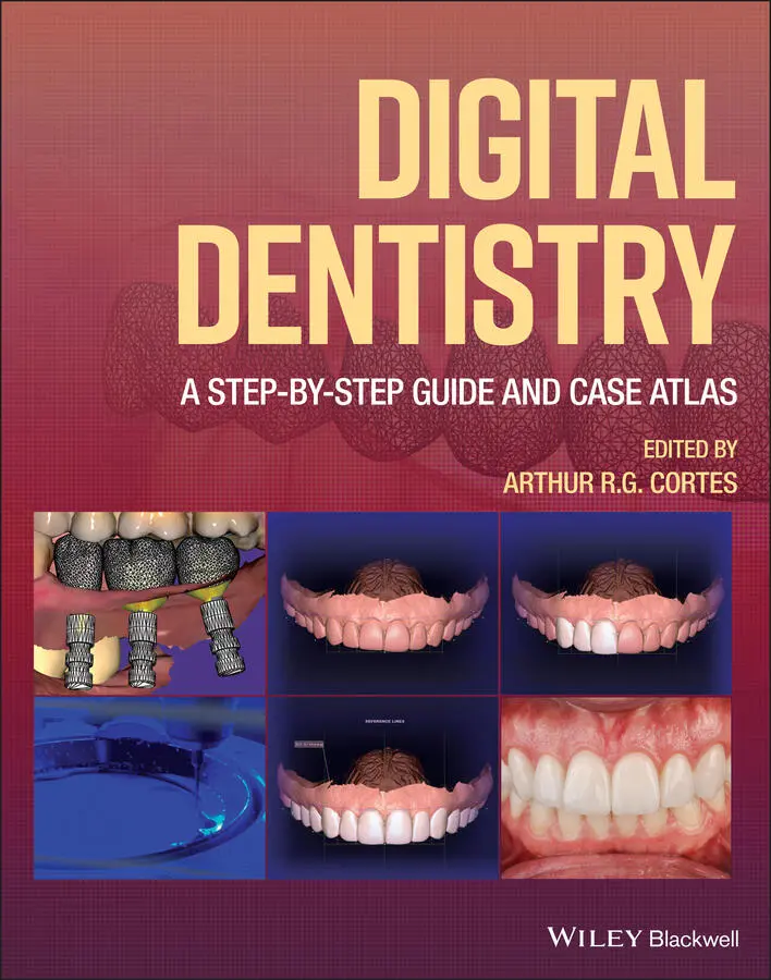
Digital Dentistry
Здесь есть возможность читать онлайн «Digital Dentistry» — ознакомительный отрывок электронной книги совершенно бесплатно, а после прочтения отрывка купить полную версию. В некоторых случаях можно слушать аудио, скачать через торрент в формате fb2 и присутствует краткое содержание. Жанр: unrecognised, на английском языке. Описание произведения, (предисловие) а так же отзывы посетителей доступны на портале библиотеки ЛибКат.
- Название:Digital Dentistry
- Автор:
- Жанр:
- Год:неизвестен
- ISBN:нет данных
- Рейтинг книги:5 / 5. Голосов: 1
-
Избранное:Добавить в избранное
- Отзывы:
-
Ваша оценка:
Digital Dentistry: краткое содержание, описание и аннотация
Предлагаем к чтению аннотацию, описание, краткое содержание или предисловие (зависит от того, что написал сам автор книги «Digital Dentistry»). Если вы не нашли необходимую информацию о книге — напишите в комментариях, мы постараемся отыскать её.
A guide to all current basic digital imaging and CAD-CAM procedures, with an emphasis on the most popular systems and software programs. An atlas of multidisciplinary cases that were treated with digital dentistry, from diagnosis and treatment planning to execution and follow-up, in order of complexity Assessment of the scientific basis for using digital dentistry in each category A presentation of clinical cases to support the use of digital methodologies in all relevant scenarios An exploration of the role of digital dentistry in dental public health, preventive dentistry, and dental education Ideal for dental clinicians—general practitioners and specialists—as well as all other dental professionals, such as dental technologists, dental hygienists, and dental students,
is an essential tool and reference work to help dental practitioners streamline and update their practice with the most up-to-date technologies.
Digital Dentistry — читать онлайн ознакомительный отрывок
Ниже представлен текст книги, разбитый по страницам. Система сохранения места последней прочитанной страницы, позволяет с удобством читать онлайн бесплатно книгу «Digital Dentistry», без необходимости каждый раз заново искать на чём Вы остановились. Поставьте закладку, и сможете в любой момент перейти на страницу, на которой закончили чтение.
Интервал:
Закладка:
4 Chapter 4Figure 4.1 Gingival retraction with double‐cord packing for two CAD‐CAM lami...Figure 4.2 Finish line preparation (left) and ideal gingival retraction at t...Figure 4.3 Clinical intraoral view of a scanbody attached to an implant (bot...Figure 4.4 The scanbody position is recorded by the intraoral scanner.Figure 4.5 The digital alignment of the implant allows the project of the im...Figure 4.6 Maxillary and mandibular scans imported in the same coordinates, ...Figure 4.7 Intraoral scans of the facebow and transfer index (yellow). The l...Figure 4.8 Virtual position of the maxillary intraoral scan aligned with the...Figure 4.9 Mandibular intraoral scan aligned with the articulated set‐up.Figure 4.10 Virtual articulator ready for dynamic occlusion analysis.Figure 4.11 Flowchart of digital esthetic analyses.Figure 4.12 Facial reference points.Figure 4.13 Main components of dentolabial esthetic analysis. Note the red l...Figure 4.14 Intraoral scan. Note the different facial reference lines assess...Figure 4.15 Digital mock‐up designed on the intraoral scan based on the resu...Figure 4.16 Alignment of facial and intraoral scans with the digital mock‐up...Figure 4.17 (a) Facial scanning cabin; (b) photographs.Figure 4.18 (a) 3D mesh without texture; (b) colored 3D mesh.Figure 4.19 Intraoral scans of the patient.Figure 4.20 Facial scan and IOS merged: (a) at rest; (b) maximum smile.Figure 4.21 Initial screen of the Exocad workflow. The initial screen of mos...Figure 4.22 Selection of type of restoration, material, and parameters. In t...Figure 4.23 If the case was not scanned within the Exocad workflow, a file b...Figure 4.24 Occlusal view of the tooth preparation leaving all margins visib...Figure 4.25 View of the antagonist model. In most cases, the occlusion will ...Figure 4.26 Alignment of the bite registration STL with the models. For this...Figure 4.27 Occlusion obtained after importing and aligning the bite registr...Figure 4.28 Autodetection of the preparation margins.Figure 4.29 Manual adjustment of the margin outline. This is done by clickin...Figure 4.30 The magic lantern tool is used to create shadows in the 3D space...Figure 4.31 Definition of the insertion axis orientation. (a) Wrong insertio...Figure 4.32 Adjustment of the cement gap thickness. A thicker cement gap cou...Figure 4.33 Minimum thickness mesh shown in red.Figure 4.34 Crown shape to be positioned onto the preparation. At this point...Figure 4.35 Tooth library selection in the “Expert” mode.Figure 4.36 Adjustment of the crown 3D dimensions and position in the dental...Figure 4.37 Smoothing of the crown surface performed after the crown is auto...Figure 4.38 Final digital crown design and position obtained with the basic ...Figure 4.39 Screenshots of the final design of the crown to be exported as a...Figure 4.40 Installation of the resulting 3D‐printed single crown of tooth 3...Figure 4.41 (a) Initial clinical intraoral view of the case. (b) Clinical as...Figure 4.42 Virtual diagnostic mock‐up.Figure 4.43 Virtual wax patterns of the three crowns.Figure 4.44 3D‐printed mock‐up try‐in result.Figure 4.45 Patient's smile after cementation of the crowns.Figure 4.46 New preparations were performed on teeth 12 and 23.Figure 4.47 New intraoral scan of the dental arch superimposed to the patien...Figure 4.48 Two new CAD‐CAM lithium disilicate crowns were cemented on the p...Figure 4.49 (a) “Import” option on Meshmixer. (b) Intraoral scans imported i...Figure 4.50 (a) Object transforming to move and rotate the crown. (b) Crown ...Figure 4.51 (a) The occlusal surface of the virtual wax pattern is slightly ...Figure 4.52 (a) Margin outlining with “Select” tool. (b) Margin outlined and...Figure 4.53 (a) New “Selection” (green). (b) The entire preparation was sele...Figure 4.54 (a) Edit menu and “Extract” tool. (b) Offset value adjustment.Figure 4.55 (a) Extraction of the preparation mesh. (b) Digital die set‐up....Figure 4.56 (a) Selection of areas to be removed. (b) Crown aspect after rem...Figure 4.57 (a) “Flip normals” function. (b) “Combine” function.Figure 4.58 (a) Mesh merging procedure. (b) Meshes finally merged.Figure 4.59 (a) Final aspect of the crown. (b) Final CAD crown on the model....Figure 4.60 Digital dies used during digital waxing of multiple single crown...Figure 4.61 Matching between the scanbody selected from the library and the ...Figure 4.62 Scanbody located in the software, enabling visualization of the ...Figure 4.63 Digital waxing of a screw‐retained implant‐supported crown.Figure 4.64 Dental implant placed and left with a healing screw.Figure 4.65 The four STL files resulting from the required intraoral scans (...Figure 4.66 Digital waxing of a screw‐retained implant‐supported crown (Virt...Figure 4.67 A CAD‐CAM lithium disilicate crown (IPS e.max Press, Ivoclar Viv...Figure 4.68 CAD‐CAM zirconia copings assessed in a research project.Figure 4.69 Procedure of outlining the emergency profile.Figure 4.70 Emergency profile adjustment.Figure 4.71 Virtual waxing of the crown.Figure 4.72 A screw‐retained crown was designed.Figure 4.73 Customized abutment (yellow).Figure 4.74 3D segmentation of the tooth.Figure 4.75 Resulting customized abutment.Figure 4.76 Zirconia custom abutment.Figure 4.77 Frontal view of the customized abutment.Figure 4.78 Milled PMMA temporary crown.Figure 4.79 Main screen of the Zirkonzahn system. Note the logical order of ...Figure 4.80 The “Import” option was selected.Figure 4.81 The “TRIOS Project” option was selected.Figure 4.82 Project details registration.Figure 4.83 Insertion axis definition for the models containing prostheses t...Figure 4.84 Digital model trimming.Figure 4.85 Preparation margin outlining.Figure 4.86 Definition of the optimal insertion axis for the fixed bridge.Figure 4.87 Cement gap thickness definition.Figure 4.88 Crown positioning.Figure 4.89 Crown shapes editing in occlusion.Figure 4.90 Adjustment and smoothing of the pontic cervical surface.Figure 4.91 Connector shape editing.Figure 4.92 Linear measurement between preparations to orientate shape and d...Figure 4.93 Final STL file of the fixed bridge.Figure 4.94 Digitally designed fixed bridge in occlusion.Figure 4.95 Fixed bridge nested into the try‐in blank.Figure 4.96 Screenshot of the CAM strategy, showing the disposition of fixed...Figure 4.97 (a) Milling preparation in the Fräsen software. (b) Milling proc...Figure 4.98 Final result of the fixed bridge milled with resin try‐in materi...Figure 4.99 Facial image with lips at rest.Figure 4.100 Facial image showing a forced smile.Figure 4.101 Facial reference lines used for esthetic planning (see section ...Figure 4.102 Tracing and reference lines for virtual wax‐up creation.Figure 4.103 Selection of the teeth shapes.Figure 4.104 Final wax‐up creation and projection on the patient's face.Figure 4.105 Incisal and gingival zenith curves.Figure 4.106 Evaluation of dental areas to be corrected. The pretreatment si...Figure 4.107 Printed model and incisal height guide.Figure 4.108 A new facial image to check the digital wax‐up transposition to...Figure 4.109 Mock‐up and incisal height guide for checking esthetic conditio...Figure 4.110 Performing tooth preparation.Figure 4.111 Gingival retraction for exposure of preparation finish line.Figure 4.112 STL file depicting precisely the preparation finish lines.Figure 4.113 Low flash intensity image for color determination.Figure 4.114 Prosthetic virtual planning. Frontal views of the patient's fac...Figure 4.115 Prosthetic virtual planning. Frontal views of the patient's for...Figure 4.116 Evaluation of the available thickness of material.Figure 4.117 Printed model with prepared teeth.Figure 4.118 Ceramic restorations on the model.Figure 4.119 Ceramic cervical edge checking.Figure 4.120 A final ceramic crown.Figure 4.121 Color homogeneity evaluation.Figure 4.122 Rubber dam application for cementation.Figure 4.123 Cementation procedure.Figure 4.124 Definitive cementation of all crowns and laminate veneers.Figure 4.125 Three‐month follow‐up results of the case.Figure 4.126 Occlusal view of the tooth remnant.Figure 4.127 Periapical radiograph of tooth 46.Figure 4.128 After tooth preparation, a digital impression was done using a ...Figure 4.129 Bite registration.Figure 4.130 Cavity evaluation and occlusal contacts.Figure 4.131 Cross‐sectional view of the preparation.Figure 4.132 The file obtained in PLY extension was sent to the ChairsideCAD...Figure 4.133 Digital design of the inlay restoration.Figure 4.134 Inlay restoration was milled using a feldspathic block of ceram...Figure 4.135 After try‐in, prior to cementation, the preparation was cleaned...Figure 4.136 Final appearance of the preparation and restoration made of fel...Figure 4.137 Polishing and finishing were done after contact points were che...Figure 4.138 Initial smile situation.Figure 4.139 3D‐printed palatal guide.Figure 4.140 Details and adaptation assessment before using the rubber dam....Figure 4.141 Photograph taken after cleaning the tooth with phosphoric acid ...Figure 4.142 Palatal guide try‐in after dentin layer is ready.Figure 4.143 Palatal shell created using the achromatic enamel resin to achi...Figure 4.144 Buccal layer created using the buccal guide before removing the...Figure 4.145 Construction of the vestibular layers of the other teeth.Figure 4.146 Final result with the same shape design that was planned before...Figure 4.147 Final smile result.Figure 4.148 Evaluation of the edentulous patient.Figure 4.149 Facial evaluation of the edentulous patient.Figure 4.150 Evaluation of the existing prostheses.Figure 4.151 Vertical dimension assessment.Figure 4.152 Digital planning of the smile.Figure 4.153 (a) Maxillary preliminary impression. (b) Mandibular preliminar...Figure 4.154 (a) UTS CAD. (b) UTS CAD BP measurement. (c) CAD CE measurement...Figure 4.155 (a) Papillameter. (b) Papillameter measurement.Figure 4.156 (a) Digitally mounted casts. (b) 3D bite plate design.Figure 4.157 3D bite plate.Figure 4.158 (a) Closed mouth impression movement 1. (b) Closed mouth impres...Figure 4.159 (a) UTS CAD CE measurement. (b) UTS CAD BP measurement.Figure 4.160 (a) Gnathometer CAD stylus. (b) Gnathometer CAD striking plate....Figure 4.161 (a) Gnathometer fixed intraoral. (b) Verification of VDO. (c) P...Figure 4.162 Form selector.Figure 4.163 (a) SR Phonares II age characteristics. (b) SR Phonares II livi...Figure 4.164 (a) Virtual models. (b) Virtual tooth arrangement. (c) Virtual ...Figure 4.165 (a) Monoblock try-in side. (b) Monoblock try-in straight.Figure 4.166 (a) Smile side profile full. (b) Smile profile front. (c) Smile...Figure 4.167 Monoblock try-in with modifications.Figure 4.168 Software finalization.Figure 4.169 (a) Ivotion disk. (b) Shell Geometry. (c) True monolithic manuf...Figure 4.170 (a) Carbide burs and diamond disk. (b) Diamond disk individuali...Figure 4.171 (a,b) Final polished dentures.Figure 4.172 (a) Side smile close‐up. (b) Front smile close‐up. (c) Candid s...Figure 4.173 (a) Edentulous situation. (b) Existing situation. (c) New prost...Figure 4.174 (a) Reference denture. (b) Existing denture. (c) 360 Reference ...Figure 4.175 A full‐arch implant‐supported fixed prosthesis, designed using ...Figure 4.176 3D‐printed crowns used in a research project.Figure 4.177 (a) Temporary prostheses designed on DentalCAD (Exocad). (b) Vi...Figure 4.178 Temporary prostheses on the 3D printer software (FlashDLPrint®,...Figure 4.179 Temporary prosthesis finalized and waiting for removal from the...Figure 4.180 Temporary prosthesis make‐up using Vita Enamic® stains kit (Vit...Figure 4.181 Importing the initial file.Figure 4.182 Model positioning before mesh cleaning.Figure 4.183 (a–g) Mesh cleaning regarding one region.Figure 4.184 (a,b) Mesh cleaning throughout the model.Figure 4.185 Visualizing mesh triangles.Figure 4.186 Decreasing brush size.Figure 4.187 Selecting the outermost triangles of the mesh.Figure 4.188 (a,b) Completing mesh edge smoothing.Figure 4.189 (a,b) Creating model base.Figure 4.190 Initial steps for making the model solid.Figure 4.191 Finalized, solid model.Figure 4.192 Finalizing the process for making the model hollow.Figure 4.193 (a,b) Initial procedures for cutting the plane.Figure 4.194 (a–c). Final procedures for cutting the plane.Figure 4.195 Exporting the file.
Читать дальшеИнтервал:
Закладка:
Похожие книги на «Digital Dentistry»
Представляем Вашему вниманию похожие книги на «Digital Dentistry» списком для выбора. Мы отобрали схожую по названию и смыслу литературу в надежде предоставить читателям больше вариантов отыскать новые, интересные, ещё непрочитанные произведения.


Обсуждение, отзывы о книге «Digital Dentistry» и просто собственные мнения читателей. Оставьте ваши комментарии, напишите, что Вы думаете о произведении, его смысле или главных героях. Укажите что конкретно понравилось, а что нет, и почему Вы так считаете.