Olivier Cavalie - Surface Displacement Measurement from Remote Sensing Images
Здесь есть возможность читать онлайн «Olivier Cavalie - Surface Displacement Measurement from Remote Sensing Images» — ознакомительный отрывок электронной книги совершенно бесплатно, а после прочтения отрывка купить полную версию. В некоторых случаях можно слушать аудио, скачать через торрент в формате fb2 и присутствует краткое содержание. Жанр: unrecognised, на английском языке. Описание произведения, (предисловие) а так же отзывы посетителей доступны на портале библиотеки ЛибКат.
- Название:Surface Displacement Measurement from Remote Sensing Images
- Автор:
- Жанр:
- Год:неизвестен
- ISBN:нет данных
- Рейтинг книги:4 / 5. Голосов: 1
-
Избранное:Добавить в избранное
- Отзывы:
-
Ваша оценка:
Surface Displacement Measurement from Remote Sensing Images: краткое содержание, описание и аннотация
Предлагаем к чтению аннотацию, описание, краткое содержание или предисловие (зависит от того, что написал сам автор книги «Surface Displacement Measurement from Remote Sensing Images»). Если вы не нашли необходимую информацию о книге — напишите в комментариях, мы постараемся отыскать её.
Surface Displacement Measurement from Remote Sensing Images — читать онлайн ознакомительный отрывок
Ниже представлен текст книги, разбитый по страницам. Система сохранения места последней прочитанной страницы, позволяет с удобством читать онлайн бесплатно книгу «Surface Displacement Measurement from Remote Sensing Images», без необходимости каждый раз заново искать на чём Вы остановились. Поставьте закладку, и сможете в любой момент перейти на страницу, на которой закончили чтение.
Интервал:
Закладка:
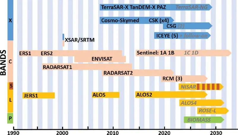
Figure 1.1. Relevant SAR missions and associated frequency bands (future missions in gray italics). For a color version of this figure, see www.iste.co.uk/cavalie/images.zip
Radar swath and pulse repetition frequency (PRF): Stripmap is the simplest working mode of a SAR system. More advanced modes can be explained relative to this mode. In stripmap, the resolution after synthesis in the azimuth direction (along-track) is given by half the antenna length La /2. The Doppler bandwidth in the azimuth is given by BDop = vs/c/ ( La/ 2), where vs/c is the satellite velocity. The PRF fP needs to be higher than BDop to avoid spectral layover in the azimuth. In contrast, in the range direction (across-track), the PRF must be limited to avoid range ambiguities or, to put it another way, the swath will be maximized if the PRF is minimized: swath < c/ 2 fP . This explains why stripmap swath is lower in X-band compared to C-band missions (a shorter antenna means higher PRFs and narrower swaths).
If higher resolution is needed, it is possible to expand BDop by electronic steering in the azimuth (the same resolution is kept in range) and thus to increase the length of observation along the orbit: this is called the spotlight mode. The counterpart is that it is no longer possible to obtain a continuous along-track imaging as in stripmap, but only sparse scenes. If a larger swath is needed, then the approach is to use ScanSAR modes: the Doppler bandwidth is shared between different subswaths. By adding an azimuth steering mode like a “reverse” spotlight, it is possible to obtain a Sentinel-1-like mode called the terrain observation by progressive scan (TOPS) mode (Zan and Guarnieri 2006). The range resolution can stay the same as the stripmap mode. In some missions with multi-incidence angles (Envisat or Radarsat-1, for instance), loss of range resolution has been mitigated for some modes by increasing the transmitted bandwidth to assure a better ground-range resolution for the lowest incidence angles.
Yaw steering: Most SAR missions use yaw steering on board, so that the spacecraft compensates for Earth rotation and the point perpendicular to the orbit is effectively at zero Doppler. Radarsat-1 was not yaw steered, which resulted in a Doppler shift of several PRFs.
Incidence angle: In contrast to optical sensors, SAR imaging sensors cannot look to the nadir, as this would create simultaneous echoes in the same pixel from both sides. In addition, the best resolution is obtained at the largest incidence angle, at the expense of lower power received due to the increased distance from the ground. The choice of the incidence angle is critical in mountainous areas due to layover on one side and shadows on the other side of mountains.
Orbit precision: This is an important parameter used to combine SAR images for interferometry. An orbit that is not precisely known will lead to an important phase gradient in the interferogram. There are three kinds of orbit that can be successively delivered:
– the first is a predicted orbit that usually comes along with the product when produced in real time;
– then, a few hours or days after the data acquisition, a restituted orbit is available with more precision;
– finally, after three or four weeks, the most precise orbit can be delivered to users, thanks to dedicated payloads and specific computing.
Nowadays, with precise orbit determination payloads onboard, orbit precision can be known at the order of a few centimeters.
Orbital tube: Recent SAR missions have integrated the use of differential interferometry in their specifications (Sentinel-1, ALOS-2, the Radarsat Constellation mission) and have put constraints on orbit housekeeping. Thus, the orbit must stay in a tube called the “orbital tube”, with a radius as small as one hundred or a few hundreds of meters to keep the perpendicular baseline small (see Chapter 4, section 4.2).
Duty cycle, down-link rate and onboard storage: The duty cycle is equivalent to the percentage of time that the radar will be able to work along the orbit. SAR systems need a lot of energy, making it impossible for them to work permanently. Depending on the design of the satellite power unit, a system can deliver between a few seconds of imaging and about 1/4 of the orbit time. There is a huge difference between very small satellites of a few hundreds of kilograms and big platforms of two or three tons. The down-link rate and onboard storage capacity are often two key elements that usually come together. A data relay satellite is sometimes helpful to cope with all the constraints or avoid multiple ground antennas for down-linking, but this usually needs a laser link and data relay commercial contract, which can also be quite expensive.
Instrument noise equivalent σ 0 : This parameter is very important when looking at amplitude images. It gives the minimum value that can be reached by the system for an elementary pixel, but entails lower values with multi-looking (see Chapter 3). It varies in range along the swath, and the specification must deliver the worst case: in general, the best values are in the middle of the swath where the antenna gain is maximum. This parameter affects measurements for ground motion: if its value is too poor, then some surfaces that have low backscattering coefficients will not be properly estimated, for instance asphalted roads, tarmacs and even sand in the desert.
Polarization: The design of the antenna sub-system determines what polarization should be implemented. For ground displacement purposes, as the signal-to-noise ratio (SNR) is more favorable, co-polarized data are mainly used, and it is difficult to say whether using HH and VV for offset tracking or InSAR techniques are more advantageous. The use of dual polarization, HH+HV or VV+VH, or quad polarization (HH+HV+VV+VH) is more relevant for other remote sensing applications, such as classification, forest extents and heights, maritime surveillance, pollution at sea or other change detection characterizations. Furthermore, the use of quad polarization generally reduces the swath and azimuth resolution by a factor of two, and thus the size of the archive in this mode is less important.
1.1.3. Parameters specific to optical missions
Pushbroom: A pushbroom camera consists of an optical system projecting an image onto a linear array of sensors. Usually, a focal plane is composed of several time delay integration (TDI) image sensors, mounted in a staggered configuration. The image is directly built at the sensor level. Charge-coupled device (CCD) sensors are used where ultra-low noise is preferred, and now complementary metal oxide semiconductor (CMOS) matrix detectors are increasingly used.
Stereo, tri-stereo and more: To build a disparity map (see Chapter 2), at least two stereo images from separate view angles are necessary. It is possible to combine more images (tri-stereo or even more) to build a more precise map. With four images, all faces of buildings may be seen, and it is possible to build a digital elevation model and associated pixel values. The different images over a geographical point are taken from different incidence angles. If they are taken with the same satellite, then they will be asynchronous. If they are taken with a constellation of satellites on the same orbit, then they may be synchronous, such as with the Co3D system. Asynchronous images imply two acquisition instants. If the delay is a few seconds, mobile elements (such as terrestrial vehicles, bots, planes) or clouds will alter the raw displacement measure. If the delay is a few weeks or months, some buildings may appear or disappear. Evolution of agricultural landscape will also alter the match between the images.
Читать дальшеИнтервал:
Закладка:
Похожие книги на «Surface Displacement Measurement from Remote Sensing Images»
Представляем Вашему вниманию похожие книги на «Surface Displacement Measurement from Remote Sensing Images» списком для выбора. Мы отобрали схожую по названию и смыслу литературу в надежде предоставить читателям больше вариантов отыскать новые, интересные, ещё непрочитанные произведения.


Обсуждение, отзывы о книге «Surface Displacement Measurement from Remote Sensing Images» и просто собственные мнения читателей. Оставьте ваши комментарии, напишите, что Вы думаете о произведении, его смысле или главных героях. Укажите что конкретно понравилось, а что нет, и почему Вы так считаете.