Liuping Wang - PID Control System Design and Automatic Tuning using MATLAB/Simulink
Здесь есть возможность читать онлайн «Liuping Wang - PID Control System Design and Automatic Tuning using MATLAB/Simulink» — ознакомительный отрывок электронной книги совершенно бесплатно, а после прочтения отрывка купить полную версию. В некоторых случаях можно слушать аудио, скачать через торрент в формате fb2 и присутствует краткое содержание. Жанр: unrecognised, на английском языке. Описание произведения, (предисловие) а так же отзывы посетителей доступны на портале библиотеки ЛибКат.
- Название:PID Control System Design and Automatic Tuning using MATLAB/Simulink
- Автор:
- Жанр:
- Год:неизвестен
- ISBN:нет данных
- Рейтинг книги:3 / 5. Голосов: 1
-
Избранное:Добавить в избранное
- Отзывы:
-
Ваша оценка:
PID Control System Design and Automatic Tuning using MATLAB/Simulink: краткое содержание, описание и аннотация
Предлагаем к чтению аннотацию, описание, краткое содержание или предисловие (зависит от того, что написал сам автор книги «PID Control System Design and Automatic Tuning using MATLAB/Simulink»). Если вы не нашли необходимую информацию о книге — напишите в комментариях, мы постараемся отыскать её.
PID Control System Design and Automatic Tuning using MATLAB Provides unique coverage of PID Control of unmanned aerial vehicles (UAVs), including mathematical models of multi-rotor UAVs, control strategies of UAVs, and automatic tuning of PID controllers for UAVs
Provides detailed descriptions of automatic tuning of PID control systems, including relay feedback control systems, frequency response estimation, Monte-Carlo simulation studies, PID controller design using frequency domain information, and MATLAB/Simulink simulation and implementation programs for automatic tuning Includes 15 MATLAB/Simulink tutorials, in a step-by-step manner, to illustrate the design, simulation, implementation and automatic tuning of PID control systems Assists lecturers, teaching assistants, students, and other readers to learn PID control with constraints and apply the control theory to various areas. Accompanying website includes lecture slides and MATLAB/ Simulink programs
is intended for undergraduate electrical, chemical, mechanical, and aerospace engineering students, and will greatly benefit postgraduate students, researchers, and industrial personnel who work with control systems and their applications.
PID Control System Design and Automatic Tuning using MATLAB/Simulink — читать онлайн ознакомительный отрывок
Ниже представлен текст книги, разбитый по страницам. Система сохранения места последней прочитанной страницы, позволяет с удобством читать онлайн бесплатно книгу «PID Control System Design and Automatic Tuning using MATLAB/Simulink», без необходимости каждый раз заново искать на чём Вы остановились. Поставьте закладку, и сможете в любой момент перейти на страницу, на которой закончили чтение.
Интервал:
Закладка:
then there are two real poles located at
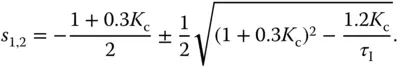
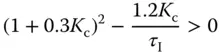
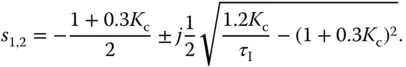
If the quantity
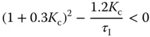
then there are two complex poles located at
The closed-loop system is stable as long as is positive and .
Applying the final value theorem, we calculate
(1.22) 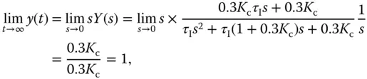
where the steady-state value is equal to the reference signal, and it is independent of the value of integral time constant . Figure 1.6 shows for the same as in Example 1.1 the closed-loop step response with and , respectively. It is seen that as reduces, the closed-loop response speed becomes faster. Nevertheless, the steady-state responses with both values are equal to one.
It is often the case that the output of a PI control system exhibits overshoot to a step reference signal. The percentage of overshoot increases as higher control performance demanded. This may cause a conflict in the PI control performance specifications: on the one hand a fast control system response is desired, and yet on the other hand, the overshoot is not desirable when step reference changes are performed. The overshooting problem in reference change could be reduced by a small change in the configuration of the PI controller. This small change is to put the proportional control on the output signal  , instead of the feedback error
  . More specifically, the control signal
  is calculated using the following relation,
(1.23) 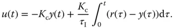
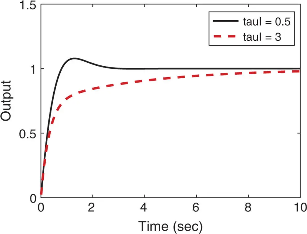
Figure 1.6Closed-loop step response of a PI control system ( Example 1.2).
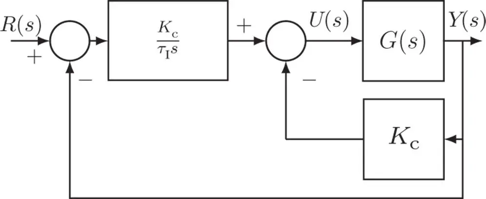
Figure 1.7 IP controller structure.
Applying a Laplace transform to this equation leads to the Laplace transform of the controller output in relation to the reference and the output as
(1.24) 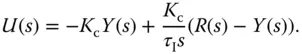
Figure 1.7shows a block diagram of this PI closed- loop control configuration. This type of implementation is called an IP controller in the literature, which is an alternative PI controller configuration. In Section 2.4, this PI controller structure is examined in the context of a reference filter within the framework of a two degrees of freedom control system. To demonstrate how this simple modification in the PI controller configuration can reduce the overshoot effect, we examine the following example.
Example 1.3
Assume that the plant is described by the transfer function:
(1.25) 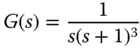
and the PI controller has the parameters: , 2. Find the closed-loop transfer function between the reference signal and the output signal for the original PI controller structure (see Figure 1.5) and the IP controller structure (see Figure 1.7), and compare their closed-loop step responses.
Solution. With the PI controller in the original structure, the closed-loop transfer function between the reference signal and the output signal is calculated using,
(1.26) 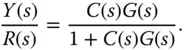
By substituting the plant transfer function (1.25) and the PI controller structure (1.16), the closed-loop transfer function is
(1.27) 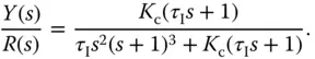
With the PI controller in the IP structure, the Laplace transform of the control signal is defined by (1.24). By substituting this control signal into the Laplace transform of the output via the following equation,
(1.28) 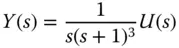
re-grouping and simplification lead to the closed-loop transfer function:
(1.29) 
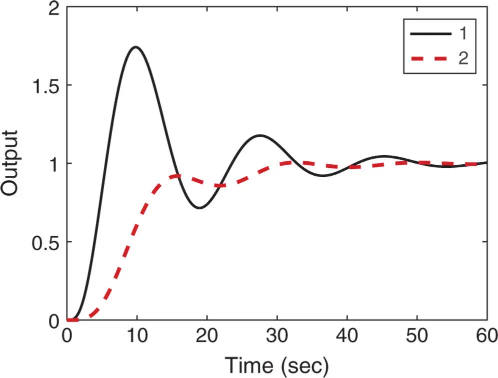
Figure 1.8Closed-loop step response of PI control system ( Example 1.3). Key: line (1) response from the original structure; line (2) response from the IP structure.
By comparing the closed-loop transfer function (1.27) from the original PI controller structure with the one (1.29) from the alternative structure, we notice that both transfer functions have the same denominator, however, the one from the original structure has a zero at . Because of this zero, the original closed-loop step response may have an overshoot.
Indeed, the closed-loop step responses for both structures are simulated and compared in Figure 1.8, which shows that the original PI closed-loop control system has a large overshoot; in contrast, the IP closed-loop control system has reduced this overshoot. The penalty for reducing the overshoot is the slower reference response speed.
The closed-loop transfer function obtained with IP controller structure can also be interpreted as a two degrees of freedom control system with a reference filter . This topic will be further discussed in Section 2.4.2.
Читать дальшеИнтервал:
Закладка:
Похожие книги на «PID Control System Design and Automatic Tuning using MATLAB/Simulink»
Представляем Вашему вниманию похожие книги на «PID Control System Design and Automatic Tuning using MATLAB/Simulink» списком для выбора. Мы отобрали схожую по названию и смыслу литературу в надежде предоставить читателям больше вариантов отыскать новые, интересные, ещё непрочитанные произведения.


Обсуждение, отзывы о книге «PID Control System Design and Automatic Tuning using MATLAB/Simulink» и просто собственные мнения читателей. Оставьте ваши комментарии, напишите, что Вы думаете о произведении, его смысле или главных героях. Укажите что конкретно понравилось, а что нет, и почему Вы так считаете.