Engineering Solutions for CO2 Conversion
Здесь есть возможность читать онлайн «Engineering Solutions for CO2 Conversion» — ознакомительный отрывок электронной книги совершенно бесплатно, а после прочтения отрывка купить полную версию. В некоторых случаях можно слушать аудио, скачать через торрент в формате fb2 и присутствует краткое содержание. Жанр: unrecognised, на английском языке. Описание произведения, (предисловие) а так же отзывы посетителей доступны на портале библиотеки ЛибКат.

- Название:Engineering Solutions for CO2 Conversion
- Автор:
- Жанр:
- Год:неизвестен
- ISBN:нет данных
- Рейтинг книги:3 / 5. Голосов: 1
-
Избранное:Добавить в избранное
- Отзывы:
-
Ваша оценка:
Engineering Solutions for CO2 Conversion: краткое содержание, описание и аннотация
Предлагаем к чтению аннотацию, описание, краткое содержание или предисловие (зависит от того, что написал сам автор книги «Engineering Solutions for CO2 Conversion»). Если вы не нашли необходимую информацию о книге — напишите в комментариях, мы постараемся отыскать её.
Engineering Solutions for CO2 Conversion — читать онлайн ознакомительный отрывок
Ниже представлен текст книги, разбитый по страницам. Система сохранения места последней прочитанной страницы, позволяет с удобством читать онлайн бесплатно книгу «Engineering Solutions for CO2 Conversion», без необходимости каждый раз заново искать на чём Вы остановились. Поставьте закладку, и сможете в любой момент перейти на страницу, на которой закончили чтение.
Интервал:
Закладка:
The Navier–Stokes equations result from a mass and momentum balance on an infinitesimal control volume within the fluid being studied. The mass conservation equation reads
(2.1) 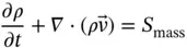
where ρ is the density of the fluid, t denotes the time,  is the velocity vector associated with the infinitesimal control volume, and S massis a mass source term. Mass source terms are crucial to the description of reactive flows, as it occurs in CO 2chemisorption in packed columns and in CO 2utilization by chemical conversion, for instance. On the other hand, the momentum equation is the second Newton's law applied to the infinitesimal control volume, whereby the sum of forces equals its acceleration. The momentum balance in one of its simplest forms is expressed as
(2.2) 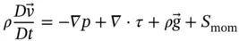
where flow incompressibility is assumed and p denotes pressure, τ is the viscous stress tensor,  is the acceleration of gravity, and D denotes the material derivative. Momentum source terms S momare helpful when the flow in a porous media is to be considered, for instance, as will be described in Section 2.2.
Finally, on the opposite end of the time‐ and length‐scale spectrum, process engineering simulations perform mass balances coupled with the equations that define the functioning of each device within an entire plant or part of it. The body of literature dealing with the application of process simulations in the field of CCSU is considerable, and as of today, process simulations remain the most widely used simulation approach in the field of CCSU. Process simulations are used to test new plant configurations, for instance, and give a general overview of the techno‐economic viability of CCSU processes, although the information lacks detail on the physical phenomena taking place within each unit process.
Simulations can therefore give valuable insight into CCSU technologies, which would be otherwise rather expensive to obtain if only experimental methods were to be applied. This chapter aims at providing the reader with a summary of the capabilities of CFD simulation techniques across the field of CCSU, from carbon capture to sequestration and utilization. Particular emphasis is to be put on those specifics that have already undergone comprehensive validation, with the aim of letting the reader know the applications where these models can be applied most confidently.
2.2 Multi‐scale Approach for CFD Simulation of Amine Scrubbers
As of today, amine scrubbing in packed columns remains the most advanced method for CO 2capture, having been deployed commercially for some years [5]. Accordingly, it has also received the greatest attention in terms of CFD modeling among all of the CCSU methods available. High‐fidelity simulations of the entire absorber describing the reactive multiphase flow within are, however, far beyond computational capacity. For this reason, the CFD modeling of amine scrubbers must be undertaken using a multi‐scale perspective. Although at present, the boundaries between scales are very clear in every CFD study on structured packings, these boundaries will be blurred in the future with the upcoming of more powerful computational resources.
An interesting multi‐scale approach for amine‐based absorbers was proposed by Raynal and Royon‐Lebeaud [6], and reviewed by Raynal et al. [7], who divided the modeling in the three scales illustrated in Figure 2.2. First off, two‐dimensional (2‐D) simulations were used at the small scale to represent the gravity‐driven liquid flow falling down the corrugations of the packing by using an interface tracking numerical technique named Volume‐of‐Fluid (VOF) method. The latter introduces an additional conservation equation for a colour function f , the volume fraction, which varies within the closed interval from 0 through 1. Cells within the mesh with values at both ends of that range correspond to either phase, whereas values in between correspond to the interface. The VOF method has proved a useful tool for the description of a number of free surface interface problems across many engineering fields. It ideally requires however the use of adaptive grids or in the case of fixed grids at least a greater resolution in those cells that are expected to contain the interface [8]. This requirement comes motivated by the discontinuous character of gas–liquid interfaces in Nature, whereas an unnatural transition area between phases appears instead of a sharp interface when using the VOF algorithm. The results can therefore be affected by substantial errors if the mesh is not treated conveniently in the vicinity of the interface. Moreover, the VOF method is characterized by the assumption that the density and viscosity assigned to the interface cells are volume fraction averaged. There is therefore some variability in the density along the computational domain that results in the appearance of additional mass and momentum source terms in the conservation equations. The implications of these additional source terms are yet to be assessed and are minimized when extra mesh refinement is introduced [9]. The average film thickness and the gas–liquid interface velocity were the direct output from the calculations at the small scale in Raynal and Royon‐Lebeaud's work. Then, the authors estimated indirectly the total liquid hold‐up as the product between the average liquid film thickness from the simulation and the specific surface of the packing given by the manufacturer.
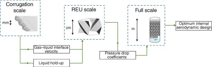
Figure 2.2This schematic illustration depicts the flow of information between the three scales proposed in the modeling strategy presented by Raynal and Royon‐Lebeaud.
Source: Adapted from Raynal and Royon‐Lebeaud [6].
At the intermediate scale, one representative elementary unit (REU, the repeating unit that forms the geometry of the packing) was represented because the pressure drop per unit length in a limited set of REUs matches that of the entire column [10]. Raynal and Royon‐Lebeaud [6] proposed a single‐phase flow approach (with only gas phase) at the REU level, although in their case, information from the small scale would be fed into their REU set‐up in order to account for the effect of the presence of liquid. To do so, two modifications at the REU scale setup were introduced. On the one hand, instead of a non‐slip boundary condition on the packing walls, i.e. velocity equal zero, the authors established a fixed velocity (the gas–liquid interface velocity obtained at the small scale). On the other hand, and in order to compare their data with a set of experiments including gas and liquid flow, the authors corrected the F ‐factor by the liquid hold‐up obtained from the average liquid film thickness of the small‐scale simulations. The F ‐factor F is a measure of the kinetic energy of the gas phase that enters the packed bed and comes determined by the product between the superficial velocity and the square root of the gas‐phase density. The corrected value of the F ‐factor F ′ is obtained by dividing it over the volume occupied by the gas phase per unit volume of packing, that is, the complementary value of the liquid hold‐up. A greater F ‐factor then, than that of a dry simulation, is obtained for the same value of the gas superficial velocity. This is in accordance with the narrowing effect that the presence of the liquid phase has on the channels through which the gas flows, and therefore, greater gas pressure drops are obtained upon wet conditions. These intermediate scale calculations allowed the authors to obtain the pressure drop coefficients K in the three coordinate directions as the ratio per unit length between the pressure drop Δ P and the superficial dynamic pressure of the gas phase.
Читать дальшеИнтервал:
Закладка:
Похожие книги на «Engineering Solutions for CO2 Conversion»
Представляем Вашему вниманию похожие книги на «Engineering Solutions for CO2 Conversion» списком для выбора. Мы отобрали схожую по названию и смыслу литературу в надежде предоставить читателям больше вариантов отыскать новые, интересные, ещё непрочитанные произведения.


Обсуждение, отзывы о книге «Engineering Solutions for CO2 Conversion» и просто собственные мнения читателей. Оставьте ваши комментарии, напишите, что Вы думаете о произведении, его смысле или главных героях. Укажите что конкретно понравилось, а что нет, и почему Вы так считаете.