Thomas Commerford Martin - Inventions, Researches and Writings of Nikola Tesla
Здесь есть возможность читать онлайн «Thomas Commerford Martin - Inventions, Researches and Writings of Nikola Tesla» — ознакомительный отрывок электронной книги совершенно бесплатно, а после прочтения отрывка купить полную версию. В некоторых случаях можно слушать аудио, скачать через торрент в формате fb2 и присутствует краткое содержание. Жанр: unrecognised, на английском языке. Описание произведения, (предисловие) а так же отзывы посетителей доступны на портале библиотеки ЛибКат.
- Название:Inventions, Researches and Writings of Nikola Tesla
- Автор:
- Жанр:
- Год:неизвестен
- ISBN:нет данных
- Рейтинг книги:3 / 5. Голосов: 1
-
Избранное:Добавить в избранное
- Отзывы:
-
Ваша оценка:
Inventions, Researches and Writings of Nikola Tesla: краткое содержание, описание и аннотация
Предлагаем к чтению аннотацию, описание, краткое содержание или предисловие (зависит от того, что написал сам автор книги «Inventions, Researches and Writings of Nikola Tesla»). Если вы не нашли необходимую информацию о книге — напишите в комментариях, мы постараемся отыскать её.
Inventions, Researches and Writings of Nikola Tesla — читать онлайн ознакомительный отрывок
Ниже представлен текст книги, разбитый по страницам. Система сохранения места последней прочитанной страницы, позволяет с удобством читать онлайн бесплатно книгу «Inventions, Researches and Writings of Nikola Tesla», без необходимости каждый раз заново искать на чём Вы остановились. Поставьте закладку, и сможете в любой момент перейти на страницу, на которой закончили чтение.
Интервал:
Закладка:
The modifications which are applicable to other forms of converter are in many respects applicable to this, such as those pertaining more particularly to the form of the core, the relative lengths and resistances of the primary and secondary coils, and the arrangements for running or operating the same.
CHAPTER XXIV.
A Constant Current Transformer with Magnetic Shield Between Coils of Primary and Secondary.
Table of Contents
Mr. Tesla has applied his principle of magnetic shielding of parts to the construction also of transformers, the shield being interposed between the primary and secondary coils. In transformers of the ordinary type it will be found that the wave of electromotive force of the secondary very nearly coincides with that of the primary, being, however, in opposite sign. At the same time the currents, both primary and secondary, lag behind their respective electromotive forces; but as this lag is practically or nearly the same in the case of each it follows that the maximum and minimum of the primary and secondary currents will nearly coincide, but differ in sign or direction, provided the secondary be not loaded or if it contain devices having the property of self-induction. On the other hand, the lag of the primary behind the impressed electromotive force may be diminished by loading the secondary with a non-inductive or dead resistance—such as incandescent lamps—whereby the time interval between the maximum or minimum periods of the primary and secondary currents is increased. This time interval, however, is limited, and the results obtained by phase difference in the operation of such devices as the Tesla alternating current motors can only be approximately realized by such means of producing or securing this difference, as above indicated, for it is desirable in such cases that there should exist between the primary and secondary currents, or those which, however produced, pass through the two circuits of the motor, a difference of phase of ninety degrees; or, in other words, the current in one circuit should be a maximum when that in the other circuit is a minimum. To attain to this condition more perfectly, an increased retardation of the secondary current is secured in the following manner: Instead of bringing the primary and secondary coils or circuits of a transformer into the closest possible relations, as has hitherto been done, Mr. Tesla protects in a measure the secondary from the inductive action or effect of the primary by surrounding either the primary or the secondary with a comparatively thin magnetic shield or screen. Under these modified conditions, as long as the primary current has a small value, the shield protects the secondary; but as soon as the primary current has reached a certain strength, which is arbitrarily determined, the protecting magnetic shield becomes saturated and the inductive action upon the secondary begins. It results, therefore, that the secondary current begins to flow at a certain fraction of a period later than it would without the interposed shield, and since this retardation may be obtained without necessarily retarding the primary current also, an additional lag is secured, and the time interval between the maximum or minimum periods of the primary and secondary currents is increased. Such a transformer may, by properly proportioning its several elements and determining the proper relations between the primary and secondary windings, the thickness of the magnetic shield, and other conditions, be constructed to yield a constant current at all loads.
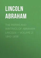
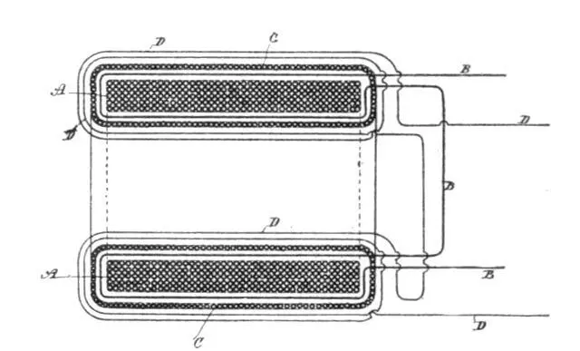 Fig. 95.
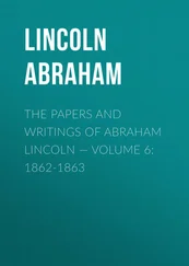
Fig. 95 is a cross-section of a transformer embodying this improvement. Fig. 96 is a similar view of a modified form of transformer, showing diagrammatically the manner of using the same.
A A is the main core of the transformer, composed of a ring of soft annealed and insulated or oxidized iron wire. Upon this core is wound the secondary circuit or coil B B. This latter is then covered with a layer or layers of annealed and insulated iron wires C C, wound in a direction at right angles to the secondary coil. Over the whole is then wound the primary coil or wire D D. From the nature of this construction it will be obvious that as long as the shield formed by the wires C is below magnetic saturation the secondary coil or circuit is effectually protected or shielded from the inductive influence of the primary, although on open circuit it may exhibit some electromotive force. When the strength of the primary reaches a certain value, the shield C, becoming saturated, ceases to protect the secondary from inductive action, and current is in consequence developed therein. For similar reasons, when the primary current weakens, the weakening of the secondary is retarded to the same or approximately the same extent.
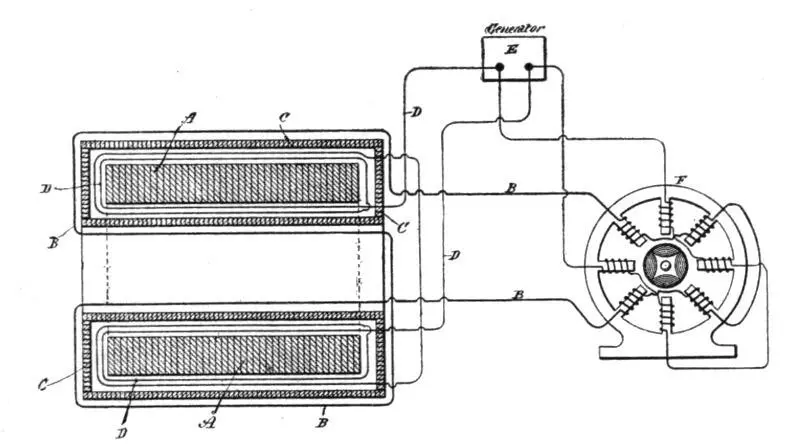 Fig. 96.
The specific construction of the transformer is largely immaterial. In Fig. 96, for example, the core A is built up of thin insulated iron plates or discs. The primary circuit D is wound next the core A. Over this is applied the shield C, which in this case is made up of thin strips or plates of iron properly insulated and surrounding the primary, forming a closed magnetic circuit. The secondary B is wound over the shield C. In Fig. 96, also, E is a source of alternating or rapidly changing currents. The primary of the transformer is connected with the circuit of the generator. F is a two-circuit alternating current motor, one of the circuits being connected with the main circuit from the source E, and the other being supplied with currents from the secondary of the transformer.
Конец ознакомительного фрагмента.
Текст предоставлен ООО «ЛитРес».
Прочитайте эту книгу целиком, купив полную легальную версию на ЛитРес.
Безопасно оплатить книгу можно банковской картой Visa, MasterCard, Maestro, со счета мобильного телефона, с платежного терминала, в салоне МТС или Связной, через PayPal, WebMoney, Яндекс.Деньги, QIWI Кошелек, бонусными картами или другим удобным Вам способом.
Интервал:
Закладка:
Похожие книги на «Inventions, Researches and Writings of Nikola Tesla»
Представляем Вашему вниманию похожие книги на «Inventions, Researches and Writings of Nikola Tesla» списком для выбора. Мы отобрали схожую по названию и смыслу литературу в надежде предоставить читателям больше вариантов отыскать новые, интересные, ещё непрочитанные произведения.


Обсуждение, отзывы о книге «Inventions, Researches and Writings of Nikola Tesla» и просто собственные мнения читателей. Оставьте ваши комментарии, напишите, что Вы думаете о произведении, его смысле или главных героях. Укажите что конкретно понравилось, а что нет, и почему Вы так считаете.