Rajib Taid - Mobile Communications Systems Development
Здесь есть возможность читать онлайн «Rajib Taid - Mobile Communications Systems Development» — ознакомительный отрывок электронной книги совершенно бесплатно, а после прочтения отрывка купить полную версию. В некоторых случаях можно слушать аудио, скачать через торрент в формате fb2 и присутствует краткое содержание. Жанр: unrecognised, на английском языке. Описание произведения, (предисловие) а так же отзывы посетителей доступны на портале библиотеки ЛибКат.
- Название:Mobile Communications Systems Development
- Автор:
- Жанр:
- Год:неизвестен
- ISBN:нет данных
- Рейтинг книги:5 / 5. Голосов: 1
-
Избранное:Добавить в избранное
- Отзывы:
-
Ваша оценка:
Mobile Communications Systems Development: краткое содержание, описание и аннотация
Предлагаем к чтению аннотацию, описание, краткое содержание или предисловие (зависит от того, что написал сам автор книги «Mobile Communications Systems Development»). Если вы не нашли необходимую информацию о книге — напишите в комментариях, мы постараемся отыскать её.
Mobile Communications Systems Development: A Practical Approach for System Understanding, Implementation and Deployment In-depth chapters cover the entire protocol stack from the Physical (PHY) to the Application layer, discuss theoretical and practical considerations, and describe software implementation based on the 3GPP standardized technical specifications. The book includes figures, tables, and sample computer code to help readers thoroughly comprehend the functions and underlying concepts of a mobile communications network. Each chapter includes an introduction to the topic and a chapter summary. A full list of references, and a set of exercises are also provided at the end of the book to test comprehension and strengthen understanding of the material. Written by a respected professional with more than 20 years’ experience in the field, this highly practical guide:
Provides detailed introductory information on GSM, GPRS, UMTS, and LTE mobile communications systems and networks Describes the various aspects and areas of the LTE system air interface and its protocol layers Covers troubleshooting and resolution of mobile communications systems and networks issues Discusses the software and hardware platforms used for the development of mobile communications systems network elements Includes 5G use cases, enablers, and architectures that cover the 5G NR (New Radio) and 5G Core Network
is perfect for graduate and postdoctoral students studying mobile communications and telecom design, electronic engineering undergraduate students in their final year, research and development engineers, and network operation and maintenance personnel.
Mobile Communications Systems Development — читать онлайн ознакомительный отрывок
Ниже представлен текст книги, разбитый по страницам. Система сохранения места последней прочитанной страницы, позволяет с удобством читать онлайн бесплатно книгу «Mobile Communications Systems Development», без необходимости каждый раз заново искать на чём Вы остановились. Поставьте закладку, и сможете в любой момент перейти на страницу, на которой закончили чтение.
Интервал:
Закладка:
Between GSM BSC and MSC: A‐Interface
The logical A‐interface is used to exchange signaling messages between the GSM BSC and the MSC. Over the A‐interface, the following types of messages are exchanged between the BSC and MSC.
Base Station Management Application Part (BSSMAP)
Signaling messages for various functions and procedures performed between the BSC and MSC are classified into BSSMAP types. BSSMAP messages, between BSC and MSC, are also encoded/decoded and are described in a tabular format similar to the air interface Layer 3 messages. However, unlike the Layer 3 messages, BSSMAP messages do not contain a message header. Each BSSAMP message starts with its message type, followed by the associated IEs.
Direct Transfer Application Part (DTAP)
DTAP messages are exchanged between the UE and MSC only. All the air interface Layer 3 CC and MM signaling messages that are transparently forwarded by the BSC, received from the MS to the MSC without processing by BSC, are classified into DTAP types. DTAP messages are the air interface Layer 3 messages with a header containing protocol discriminator information in the header of every message that is exchanged between the MS and MSC. Because of this, the DTAP message is encoded and decoded as described in Section 4.1.1.
Example 4.8LTE NAS Layer: Downlink NAS Transport: MME to eNodeB
Figure 4.8shows the definition of the downlink NAS transport message from the LTE/EPC MME to the eNodeB.
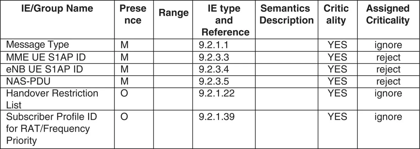
Figure 4.8 LTE/EPS MME‐ENodeB: S1‐AP: downlink NAS transport.
Source: © 2014. 3GPP ™ TSs and TRs are the property of ARIB, ATIS, CCSA, ETSI, TSDSI, TTA and TTC who jointly own the copyright in them. © 2014, 3GPP.
Between GSM BSC and SGSN: Gb‐Interface
The Gb‐interface is used to exchange signaling messages between the GSM BSC and the SGSN. Over the Gb‐interface, the following types of messages are exchanged between the BSC and SGSN of a GPRS network.
Network Service protocol layer; refer to 3GPP TS 48.016 [135].
BSS GPRS Protocol (BSSGP) protocol layer; refer to 3GPP TS 48.018 [136].
NS and BSSGP layer messages are also encoded/decoded and are described in a tabular format similar to the air interface Layer 3 messages. However, unlike the Layer 3 messages, NS and BSSGP layer messages do not contain a message header. Each NS and BSSGP layer message starts with their message type, followed by the associated IEs.
Between UMTS RNC – CN; LTE E‐UTRAN and CN; 5G NG‐RAN and CN
The UMTS RANAP, over the Iu interface between RNC and CN, uses the ASN.1 notation for describing the signaling message between RNC and the CN. The LTE/EPS S1‐AP, between eNodeB and MME, and X2‐AP, between two eNodeBs, also uses the ASN.1 notation for encoding and decoding of signaling message over the S1 and X2 interface. Similarly, the 5G system NG‐AP, between NG‐RAN/gNB and AMF, and XN‐AP, between two gNB, also use the ASN.1 notation for encoding and decoding of signaling message over the NG and Xn interfaces. Protocol messages specifications using ASN.1 notation was described earlier in Section 4.1.5. Note that the messages exchanged between UMTS RNC – CN; LTE E‐UTRAN and CN; 5G NG‐RAN and 5G core are also described using tabular notation. Example 4.8illustrates the tabular definitions of a message described in a tabular format.
The NAS‐PDU IE, which is a mandatory one, in the downlink NAS transport message contains the message to be communicated from the MME to the UE.
Chapter Summary
This chapter presented the CSN.1, ASN.1, direct, indirect, tabular format, and so on and methods of describing and encoding/decoding protocol layer messages across the different mobile communications systems from the GSM to the 5G system. The peer protocol layers of network elements of a mobile communications network exchange signaling messages using a particular encoding/decoding method as described in this chapter. These encoding and decoding methods are used over their respective logical interfaces, e.g. air interface Layer 2, Layer 3, NAS layer, between RAN and CN, and so on, to exchange control plane information. In comparison to the other encoding methods described in this chapter, the CSN.1 encoding method produces more compact protocol layer messages that are to be transmitted over the GPRS air interface.
An encoding and decoding method represents the data structures of IEs of messages that are used during the software design and development of protocol layers supported by the network elements of a mobile communications network. An IE of a message may contain and may be encoded with several information. Unlike the traditional IP layer header and packet, information may be encoded/decoded even at a single bit level in a mobile communications message. Correctly encoding and decoding of an IE, its components, and the value of a control plane or data plane message is important for the successful operation of a mobile communications network. It is also important from the interworking and interoperation point of view. We then closed the chapter with the method of piggybacking of a signaling message over another signaling message, thus reducing signaling overhead, be it over the air interface or between CN elements.
5 Network Elements : Identities and Its Addressing
Introduction
This chapter covers the various identities that are used to identify and address different network elements or logical objects of mobile communications systems and networks, i.e. Global System for Mobile Communication (GSM), General Packet Radio Service (GPRS), Universal Mobile Telecommunication System (UMTS), and Long‐Term Evolution (LTE) system. Network identities used in the 5G system are described in Chapter 16. Every network element has its own identity using which the peer network element can identify the source of data received over a particular interface.
We begin with the network identities that are used at the radio access and core network (CN) domain along with their nature. A network element identity has several other aspects such as its persistency, which may be either permanent or temporary; also, an identity may have a local or global presence. A network element can have several identities, especially if it supports multiple radio access technologies (RATs). We then present the fundamental or native and mapped identity of a network element. Mapped identities are used in case of an interworking scenario where a user and its User Equipment (UE) move from one RAT to another and vice versa.
A network identity may be used by a network element to keep track of the resources allocated to another network element. Apart from the network elements, network identities are also assigned to identify and address other logical objects such as the GSM location area, GPRS routing area, and LTE/Evolved Packet System (EPS) tracking area. Such network identities are further described in Chapter 18.
5.1 Network Elements and Their Identities
A mobile communications system and network comprise numerous physical network elements or resources as well as logical objects or resources that are used as part of the design, development, implementation, and field deployment. Network elements or resource identities are logical in nature. An identity may represent a logical connection and association between two network elements. A network element, say eNodeB, may assign an identity to another network, say UE, to uniquely identify it over a particular logical interface. The network element's identities are divided into the following categories:
Читать дальшеИнтервал:
Закладка:
Похожие книги на «Mobile Communications Systems Development»
Представляем Вашему вниманию похожие книги на «Mobile Communications Systems Development» списком для выбора. Мы отобрали схожую по названию и смыслу литературу в надежде предоставить читателям больше вариантов отыскать новые, интересные, ещё непрочитанные произведения.


Обсуждение, отзывы о книге «Mobile Communications Systems Development» и просто собственные мнения читателей. Оставьте ваши комментарии, напишите, что Вы думаете о произведении, его смысле или главных героях. Укажите что конкретно понравилось, а что нет, и почему Вы так считаете.