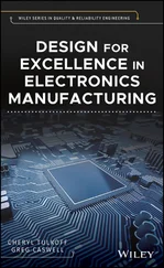
Alessandro Massaro - Electronics in Advanced Research Industries

Здесь есть возможность читать онлайн «Alessandro Massaro - Electronics in Advanced Research Industries» — ознакомительный отрывок электронной книги совершенно бесплатно, а после прочтения отрывка купить полную версию. В некоторых случаях можно слушать аудио, скачать через торрент в формате fb2 и присутствует краткое содержание. Жанр: unrecognised, на английском языке. Описание произведения, (предисловие) а так же отзывы посетителей доступны на портале библиотеки ЛибКат.

Electronics in Advanced Research Industries: краткое содержание, описание и аннотация

Предлагаем к чтению аннотацию, описание, краткое содержание или предисловие (зависит от того, что написал сам автор книги «Electronics in Advanced Research Industries»). Если вы не нашли необходимую информацию о книге — напишите в комментариях, мы постараемся отыскать её.

A one-of-a-kind examination of the latest developments in machine control 
 
In 
, accomplished electronics researcher and engineer Alessandro Massaro delivers a comprehensive exploration of the latest ways in which people have achieved machine control, including automated vision technologies, advanced electronic and micro-nano sensors, advanced robotics, and more. 
The book is composed of nine chapters, each containing examples and diagrams designed to assist the reader in applying the concepts discussed within to common issues and problems in the real-world. Combining electronics and mechatronics to show how they can each be implemented in production line systems, the book presents insightful new ways to use artificial intelligence in production line machines. The author explains how facilities can upgrade their systems to an Industry 5.0 environment. 
Electronics in Advanced Research Industries: Industry 4.0 to Industry 5.0 Advances A thorough introduction to the state-of-the-art in a variety of technological areas, including flexible technologies, scientific approaches, and intelligent automatic systems Comprehensive explorations of information technology infrastructures that support Industry 5.0 facilities, including production process simulation Practical discussions of human-machine interfaces, including mechatronic machine interface architectures integrating sensor systems and machine-to-machine (M2M) interfaces In-depth examinations of internet of things (IoT) solutions in industry, including cloud computing IoT Perfect for professionals working in electrical industry sectors in manufacturing, production line manufacturers, engineers, and members of R&D industry teams, 
 will also earn a place in libraries of technicians working in the process industry.

Electronics in Advanced Research Industries — читать онлайн ознакомительный отрывок

Ниже представлен текст книги, разбитый по страницам. Система сохранения места последней прочитанной страницы, позволяет с удобством читать онлайн бесплатно книгу «Electronics in Advanced Research Industries», без необходимости каждый раз заново искать на чём Вы остановились. Поставьте закладку, и сможете в любой момент перейти на страницу, на которой закончили чтение.

Тёмная тема
Сбросить

Интервал:

Закладка:

Сделать

4 Chapter 4Figure 4.1 Architecture model of a company information system integrating Io...Figure 4.2 Domain expert and production manager roles and relationships in a...Figure 4.3 Relationship between production manager, message broker, IoT agen...Figure 4.4 Architecture of a IoT smart manufacturing framework integrating a...Figure 4.5 (a) Rotary encoder detection system. (b) Front view of a basic en...Figure 4.6 Basic principle of potentiometer and AI wiper control.Figure 4.7 (a) LVDT 3D configuration. (b) Structure and basic principle of t...Figure 4.8 Metallic strain gauge.Figure 4.9 Load cell with a Roberval mechanism.Figure 4.10 Wheatstone bridge for load cell.Figure 4.11 Basic scheme of a laser detector.Figure 4.12 Measured accelerations in the ( x,y ) plane of a vibrating product...Figure 4.13 Measured accelerations along the z‐ axis of a vibrating pro...Figure 4.14 Konstanz Information Miner (KNIME) workflow predicting accelerat...Figure 4.15 Application of the acceleration signal processing for production...Figure 4.16 (a) Feedback control and AI corrective action. (b) Trajectory of...Figure 4.17 Basic feedback control system.Figure 4.18 Desirable gain characteristic ( ω gc, desirable gain crossove...Figure 4.19 Architecture of a multivisor AR architecture.Figure 4.20 Load balancing of the workload by parallel data flow involving t...Figure 4.21 Model representing quasi real‐time data processing involving sen...Figure 4.22 Automatism in sensor detection: (a) nanocomposite optical probe ...Figure 4.23 Quasi real‐time data processing of a sensing/actuation process m...Figure 4.24 Architecture of quasi real‐time data processing involving cloud ...Figure 4.25 UML sequence diagram describing the sensing and actuation proces...Figure 4.26 (a) Production line layout and drone monitoring in dangerous are...Figure 4.27 (a) CPU structure. (b) GPU structure and (c) related functions (...Figure 4.28 Execution time versus TPB for the exponentiation of a binary dat...Figure 4.29 Execution time versus the exponentiation n of a Float64 data mat...Figure 4.30 Execution time versus the binary matrix dimension.Figure 4.31 Comparison of GPU and CPU execution time versus the power of the...Figure 4.32 Comparison of GPU and CPU execution time versus the size of the ...Figure 4.33 Architecture integrating AI cloud server and IoT device: Industr...Figure 4.34 Architecture of an energy router system.Figure 4.35 (a) Linear prediction of energy consumption by linear regression...Figure 4.36 Thermogram of a bridge acquired by UAV. Inset: UAV adopted for t...Figure 4.37 Thermogram of Figure 4.36 setting over a threshold of 32 °C (DSS...Figure 4.38 Thermogram of a railway infrastructure.Figure 4.39 (a) Radargram of part of a bridge detected by a UAV equipped wit...Figure 4.40 Blockchain model and transactions integrating an AI controller....Figure 4.41 Blockchain architecture model.Figure 4.42 Blockchain implementation concerning a full production process d...Figure 4.43 Example of architecture implementing facilities improving dynami...Figure 4.44 Mechatronic interface board controlling three motor axes of a ro...Figure 4.45 Multiple mechatronic boards managing a production line layout ch...

5 Chapter 5Figure 5.1 (a) Robotic arm with joints connected relatively to each other. (...Figure 5.2 (a) Coordinate system determining the rotation matrix in the ( x,y Figure 5.3 (a) 3D coordinate system describing 3D translation. (b) 3D coordi...Figure 5.4 Functional scheme of a robotic arm controlled by sensors, image v...Figure 5.5 Exoskeleton configurations in industry and applied forces: (a) ar...Figure 5.6 Exoskeleton communication model integrating AI (S, pressure and t...Figure 5.7 PLC scheme enabling AI instructions (HW, hardware).Figure 5.8 PLC basic program and related table description: AND logic implem...Figure 5.9 PLC basic program and related table description: OR logic impleme...Figure 5.10 PLC basic program and related table description: hybrid AND/OR l...Figure 5.11 PLC basic program and related table description: hybrid AND/OR l...Figure 5.12 Block diagram of an electrical actuator.Figure 5.13 (a) Polarization charge of a capacitor. (b) Implementation of th...Figure 5.14 Implementation of the electrostatic actuator.Figure 5.15 Electrostatic actuator in MEMS configuration.Figure 5.16 (a) Basic principle of piezoelectric actuation. (b) Strain cause...Figure 5.17 Schematic of a piezoelectric actuator for large strain effect.Figure 5.18 Multi‐layer plate piezoelectric actuator model.Figure 5.19 DC motor by magnetic field: (a) basic principle of electromagnet...Figure 5.20 Equivalent circuit of a DC motor.Figure 5.21 Operation mode of a DC motor in four quadrants.Figure 5.22 Induction motor: (a) squirrel cage type conductor; (b)–(e) furth...Figure 5.23 (a) Mechanical scheme and (b) electrical model of a DC motor.Figure 5.24 Advanced controlled system of a DC motor by AI algorithm impleme...Figure 5.25 Systemic model of the DC motor feedback controlled by the AI mod...Figure 5.26 (a) Shunt motor and AI controlling electrical current. (b) Theor...Figure 5.27 (a) Series motor and AI controlling resistance. (b) Theoretical ...Figure 5.28 (a) DC shunt motor: modeling of the field flux control method. (...Figure 5.29 (a) DC series motor modeling. (b) Theoretical trend of the motor...Figure 5.30 Adaptive‐control diagram to automatically adapt to worker's desi...Figure 5.31 (a) Step down chopper circuit. (b) Voltage and current. (c) Step...Figure 5.32 (a) Example of IGBT and of n ‐channel MOSFET switch equivalence; ...Figure 5.33 Three‐phase VSI.Figure 5.34 (a) Scheme representing the basic principle of electrical curren...Figure 5.35 (a) SCR configuration and equivalences. (b) GTO symbols and circ...Figure 5.36 On‐state caused by gate current: (a) equivalent circuit implemen...Figure 5.37 (a) SCR and (b) GTO IV characteristics.Figure 5.38 (a) Normal switching configuration; (b) PWM signal modulation co...Figure 5.39 Example of PWM signal modulation.Figure 5.40 (a) Current‐source inverter circuit; (b) signals of the reversal...Figure 5.41 Scheme of a three‐phase CSI.Figure 5.42 (a) Uncontrolled converter configuration; (b) signal processing ...Figure 5.43 (a) Controlled converter; (b) signal processing of the converter...Figure 5.44 (a) Half‐wave rectifier circuit basic scheme; (b) half‐wave rect...Figure 5.45 (a) Voltage‐source inverter; (b) current‐source inverter.Figure 5.46 (a) Main scheme of an advanced robotic control by combining a PI...Figure 5.47 Example of an AI controlled system adjusting an arrow trajectory...Figure 5.48 (a) PID implementation circuit layout tuned by AI commands; (b) ...Figure 5.49 (a) Unsupervised process by selecting the object inline in two s...Figure 5.50 (a) Feedback loop systems. (b) Feedback system including AI feed...Figure 5.51 Pulsed spray technique in smart additive manufacturing controlle...Figure 5.52 Laser texturing technique controlled by AI.

6 Chapter 6Figure 6.1 (a) Scheme of the AFM‐SCM circuital approach. (b) Sketch of the e...Figure 6.2 (a) Microscope image of NDs deposited on a glass layer. TEM image...Figure 6.3 Post‐processed TEM images: (a) 3D image processing of silica NPs;...Figure 6.4 MWPECVD reactor and plasma generated during diamond film growth....Figure 6.5 Enhanced light of an optical fiber end embedded in a PDMS‐Au tip ...Figure 6.6 PDMS‐Au scattering efficiency versus the working wavelength for d...Figure 6.7 (a) Unit cell: modeling of PDMS with monodisperse GNs. (b) Zoomed...Figure 6.8 FEM simulations: (a) light propagating in the PDMS material; (b) ...Figure 6.9 (a) Metallic wedge in dielectric materials. (b) Transmission line...Figure 6.10 (a) Cylindrical coordinate system. (b) Spherical coordinate syst...Figure 6.11 Metallic permittivity theoretical trend: (a) gold; (b) silver; (...Figure 6.12 STRD theoretical near field radiation pattern for a gold metalli...Figure 6.13 90° metallic wedge: total TE zelectric field theoretical trend v...Figure 6.14 Optical antenna as micrometric aperture in a parallel‐plate wave...Figure 6.15 Basic scheme of pressure sensor (longitudinal section): (a) tape...Figure 6.16 (a) PDMS‐Au robotic finger (tactile pressure sensor). (b) Light ...Figure 6.17 (a) PDMS‐Au tip of the optical pressure sensor for robotic finge...Figure 6.18 Small notch sensing approach and signal detection principle and Figure 6.19 PDMS‐Au used for surveillance security systems. (a) Schematic co...Figure 6.20 PDMS‐Au 2×2 matrix pillar‐type sensor layout for liquid detectio...Figure 6.21 PDMS‐Au 2×2 matrix pillar‐type layout. The height of a single pi...Figure 6.22 (a) AFM image: topography indicating gold fillers in a PDMS matr...Figure 6.23 Absorbance trend of a PDMS/PDMS‐Au bulk type sample. Inset: radi...Figure 6.24 Total electric field confinement: sketch of a simulation for a P...Figure 6.25 2 × 2 PDMS‐Au matrix: variation of the transmitted intensity by ...Figure 6.26 Basic principle of light scattering.Figure 6.27 Sensor optical spectra: transmitted optical intensities for diff...Figure 6.28 Implementation of the sensor in a robotic finger.Figure 6.29 Microwave MEMS pressure sensor: (a) masks used for photolithogra...Figure 6.30 (a) Ring MEMS and (b) zooming of the base of the antenna.Figure 6.31 Electromagnetic absorbing material for antenna measurements.Figure 6.32 Three‐dimensional model of silica NPs embedded in a lymph node....Figure 6.33 (a) Multilayer model of an ultrasound wave propagated in human t...Figure 6.34 Unit cell model of in the mediastinum lymph node.Figure 6.35 (a) Theoretical normalized power spectrum of the diffracted wave...Figure 6.36 TEM image of synthetized silica NPs (inset: zooming of some sili...Figure 6.37 Example of functionalized silica NP synthesis by MPTS.Figure 6.38 Example of functionalized silica NP synthesis by TEOS.Figure 6.39 Current density Jcalculation characterizing insulation behavior...Figure 6.40 Measured current of diamond film growth on a silicon substrate....Figure 6.41 (a) A piece of commercial substrate. (b) Example of a ND layer d...Figure 6.42 IV characteristic of a ND sprayed layer deposited on a silicon ...

Читать дальше
Тёмная тема
Сбросить

Интервал:

Закладка:

Сделать

Похожие книги на «Electronics in Advanced Research Industries»

Представляем Вашему вниманию похожие книги на «Electronics in Advanced Research Industries» списком для выбора. Мы отобрали схожую по названию и смыслу литературу в надежде предоставить читателям больше вариантов отыскать новые, интересные, ещё непрочитанные произведения.


Отзывы о книге «Electronics in Advanced Research Industries»

Обсуждение, отзывы о книге «Electronics in Advanced Research Industries» и просто собственные мнения читателей. Оставьте ваши комментарии, напишите, что Вы думаете о произведении, его смысле или главных героях. Укажите что конкретно понравилось, а что нет, и почему Вы так считаете.

x