Alternative Liquid Dielectrics for High Voltage Transformer Insulation Systems
Здесь есть возможность читать онлайн «Alternative Liquid Dielectrics for High Voltage Transformer Insulation Systems» — ознакомительный отрывок электронной книги совершенно бесплатно, а после прочтения отрывка купить полную версию. В некоторых случаях можно слушать аудио, скачать через торрент в формате fb2 и присутствует краткое содержание. Жанр: unrecognised, на английском языке. Описание произведения, (предисловие) а так же отзывы посетителей доступны на портале библиотеки ЛибКат.
- Название:Alternative Liquid Dielectrics for High Voltage Transformer Insulation Systems
- Автор:
- Жанр:
- Год:неизвестен
- ISBN:нет данных
- Рейтинг книги:4 / 5. Голосов: 1
-
Избранное:Добавить в избранное
- Отзывы:
-
Ваша оценка:
Alternative Liquid Dielectrics for High Voltage Transformer Insulation Systems: краткое содержание, описание и аннотация
Предлагаем к чтению аннотацию, описание, краткое содержание или предисловие (зависит от того, что написал сам автор книги «Alternative Liquid Dielectrics for High Voltage Transformer Insulation Systems»). Если вы не нашли необходимую информацию о книге — напишите в комментариях, мы постараемся отыскать её.
Alternative Liquid Dielectrics for High Voltage Transformer Insulation Systems • Covers condition monitoring, diagnostic testing, applications, maintenance, and in-service experiences
• Explores current challenges and future prospects of ester-filled transformers
• Discusses significant research progress and identifies the topics in need of further emphasis
• Compares the differences and similarities between mineral oils and ester liquids
• Includes in-depth behavioral observations and performance analysis of ester-based insulating liquids
Alternative Liquid Dielectrics for High Voltage Transformer Insulation Systems: Performance Analysis and Applications
Alternative Liquid Dielectrics for High Voltage Transformer Insulation Systems — читать онлайн ознакомительный отрывок
Ниже представлен текст книги, разбитый по страницам. Система сохранения места последней прочитанной страницы, позволяет с удобством читать онлайн бесплатно книгу «Alternative Liquid Dielectrics for High Voltage Transformer Insulation Systems», без необходимости каждый раз заново искать на чём Вы остановились. Поставьте закладку, и сможете в любой момент перейти на страницу, на которой закончили чтение.
Интервал:
Закладка:
The standard IEEE C57‐104 is dedicated to MO whereas the standard IEEE C57‐155 is about Interpretation of Gases Generated in Natural Ester and Synthetic Ester‐Immersed Transformers. As all the gas ratio techniques are elaborated in IEEE C57‐104, it is used for analysis. The Duval Triangle method is mentioned as per IEEE C57‐155 and it is used with regards to the stray gassing phenomenon in natural esters under the effect of the thermal stress.
2.6.1 Standard Gas Ratios
There are several methods to infer the DGA results of a transformer, with some of them listed below. The most important hydrocarbon gases are methane (CH 4), ethane (C 2H 6), hydrogen (H 2), ethylene (C 2H 4), and acetylene (C 2H 2). These gases are taken into consideration when analyzing the gas ratios in IEC, Rogers, Doernenburg, and Duval’s triangle methods. All these gas ratio methods indicate the types of faults likely to occur in a transformer after the oils are subjected to thermal or electrical stress. The five gas ratios according to standard are: Ratio 1 (R1) = CH 4/H 2, Ratio 2 (R2) = C 2H 2/C 2H 4, Ratio 3 (R3) = C 2H 2/CH 4, Ratio 4 (R4) = C 2H 6/C 2H 2, and Ratio 5 (R5) = C 2H 4/C 2H 6.
2.6.1.1 IEC Gas Ratios
The IEC 60599 standard is one of the prevalent approaches for an elucidation of the faults occurring in a transformer, which is based on ratios of five key gases: CH 4, H 2, C 2H 4, C 2H 6, and C 2H 2. In this method, the ratios R1, R2, and R5 are measured to make the interpretation of the faults as per Tables 2.5and 2.6. A grouping of the individual codes of R1, R2, and R5 indicates the type of incipient fault. However, this method does not give very accurate results for all fault types.
2.6.1.2 Doernenburg Ratio Method
This technique uses the four ratios R1, R2, R3, and R4 for diagnostics of faults in the transformer. In this method, it is primarily determined whether a fault exists in the transformer by examining the quantity of each gas associated to a minimum concentration limit L1 as given in Table 2.7. There is a fault in the transformer if any of the gases from H 2, CH 4, C 2H 2, and C 2H 4exceeds double the recommended limit L1 and the quantity (ppm) of any one of the other two gases (C 2H 6and CO) exceeds this limit L1. This procedure is reliable only if the quantity of at least one of the gases in each ratio exceeds the limit value, otherwise oil samples may be again collected for repeated analysis. If the ratio analysis is valid, then each successive ratio is compared in the order of R1, R2, R3, R4 and the fault type is ascertained as given in Table 2.8.
Table 2.5 IEC gas ratios.
| Gas ratio | Value | Code |
|---|---|---|
| R2 = C 2H 2/C 2H 4 | R2 < 0.1 | 0 |
| 0.1≤ R2 ≤ 3 | 1 | |
| R2 > 3 | 2 | |
| R1 = CH 4/H 2 | R1 < 0.1 | 1 |
| 0.1≤ R1 ≤ 1 | 0 | |
| R1 > 1 | 2 | |
| R5 = C 2H 4/C 2H 6 | R5 < 1 | 0 |
| 1≤ R5 ≤ 3 | 1 | |
| R5 > 3 | 2 |
Table 2.6 Types of faults.
| No. | Type of fault | Code | ||
|---|---|---|---|---|
| R2 | R1 | R5 | ||
| 1 | No fault | 0 | 0 | 0 |
| 2 | Partial Discharge with low energy density | 0 | 1 | 0 |
| 3 | Partial Discharge with high energy density | 1 | 1 | 0 |
| 4 | Discharge (arc) with low energy | 1→2 | 0 | 1→2 |
| 5 | Discharge (arc) with high energy | 1 | 0 | 2 |
| 6 | Thermal faults of temperatures < 150 °C | 0 | 0 | 1 |
| 7 | Thermal faults of temperatures between 150 and 300 °C | 0 | 2 | 0 |
| 8 | Thermal faults of temperatures between 300 and 700 °C | 0 | 2 | 1 |
| 9 | Thermal faults of temperatures >700 °C | 0 | 2 | 2 |
Table 2.7 Doernenburg gas ratio method.
| Key gases | Minimum concentration L1 (ppm) |
|---|---|
| Hydrogen (H 2) | 100 |
| Methane (CH 4) | 120 |
| Carbon monoxide (CO) | 350 |
| Acetylene (C 2H 2) | 1 |
| Ethylene (C 2H 4) | 50 |
| Ethane (C 2H 6) | 65 |
Table 2.8 Types of faults by Doernenburg ratio method.
| No. | Type of fault | R1 | R2 | R3 | R4 |
|---|---|---|---|---|---|
| 1 | No fault | Conc. (H 2or CH 4or C 2H 2or C 2H 4)>2L1 and Conc. (C 2H 6and CO) 2or CH 4or C 2H 2or C 2H 4)< 2L1] | |||
| 2 | Thermal decomposition | R1 > 1 | R2 < 0.75 | R3 < 0.3 | R4 > 0.4 |
| 3 | Low‐intensity partial discharge | R1 < 0.1 | R2 = ND | R3 < 0.3 | R4 > 0.4 |
| 4 | High‐intensity arcing | 0.1 < R1 < 1 | R2 > 0.75 | R3 > 0.3 | R4 < 0.4 |
2.6.1.3 Rogers Ratio Method
In this technique, three gas ratios R1, R2, and R5 are used for the explanation of the incipient faults in a transformer. The boundaries of the gas ratios suggesting a specific fault type is given in Table 2.9. Rogers method is not dependent on specific gas concentrations for the analysis to be valid. This technique is not always suitable as the accuracy is not very good in identifying faults.
2.6.1.4 Duval’s Triangle
The Duval Triangle uses three hydrocarbon gases only, namely methane (CH 4), ethylene (C 2H 4), and acetylene (C 2H 2), to detect the fault types [75, 76]. The concentration of the gases is plotted in a triangular coordinate system. The types of faults detected by the Duval’s triangle method are given in Table 2.10. The coordinates of the fault are denoted by the points A1=%p1, A2=%p2, A3=%p3 for the percentage concentration of CH 4, C 2H 4, and C 2H 2gases, respectively. The concentration of gases in ppm are considered for CH 4= p 1, C 2H 4= p 2, and C 2H 2= p 3and are converted to triangular coordinates. The relative proportion of the three gases is calculated as below:
(2.18) 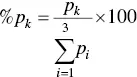
Table 2.9 Types of faults by Rogers ratio method.
| No. | Type of fault | R1 | R5 | R2 |
|---|---|---|---|---|
| 1 | No fault | 0.1 < R1 < 1 | R5 < 1 | R2 < 0.1 |
| 2 | Partial Discharge with low energy density | R1 < 0.1 | R5 < 1 | R2 < 0.1 |
| 3 | Arcing with high energy discharge | 0.1 ≤ R1 ≤ 1 | R5 > 3 | 0.1 ≤ R2 ≤ 3 |
| 4 | Low temperature thermal faults | 0.1 < R1 < 1 | 1 ≤ R5 ≤ 3 | R2 < 0.1 |
| 5 | Thermal faults of temperatures < 700 °C | R1 > 1 | 1 ≤ R5 ≤ 3 | R2 < 0.1 |
| 6 | Thermal faults of temperatures >700 °C | R1 > 1 | R5 > 3 | R2 < 0.1 |
Table 2.10 Types of faults.
| No. | Type of fault | Symbol |
|---|---|---|
| 1 | Partial discharge with low energy density | PD |
| 2 | Discharge (arc) with low energy | D1 |
| 3 | Discharge (arc) with high energy | D2 |
| 4 | Mixture of electrical and thermal faults | DT |
| 5 | Thermal faults of temperatures <300 °C | T1 |
| 6 | Thermal faults of temperatures between 300 and 700 °C | T2 |
| 7 | Thermal faults of temperatures >700 °C | T3 |
| 8 | Overheating | O |
| 9 | Stray gassing | S |
| 10 | Hot spots with carbonization of paper | C |
where k = 1, 2, 3 as per the three gases mentioned above.
Читать дальшеИнтервал:
Закладка:
Похожие книги на «Alternative Liquid Dielectrics for High Voltage Transformer Insulation Systems»
Представляем Вашему вниманию похожие книги на «Alternative Liquid Dielectrics for High Voltage Transformer Insulation Systems» списком для выбора. Мы отобрали схожую по названию и смыслу литературу в надежде предоставить читателям больше вариантов отыскать новые, интересные, ещё непрочитанные произведения.


Обсуждение, отзывы о книге «Alternative Liquid Dielectrics for High Voltage Transformer Insulation Systems» и просто собственные мнения читателей. Оставьте ваши комментарии, напишите, что Вы думаете о произведении, его смысле или главных героях. Укажите что конкретно понравилось, а что нет, и почему Вы так считаете.