Daniel Minoli - High-Density and De-Densified Smart Campus Communications
Здесь есть возможность читать онлайн «Daniel Minoli - High-Density and De-Densified Smart Campus Communications» — ознакомительный отрывок электронной книги совершенно бесплатно, а после прочтения отрывка купить полную версию. В некоторых случаях можно слушать аудио, скачать через торрент в формате fb2 и присутствует краткое содержание. Жанр: unrecognised, на английском языке. Описание произведения, (предисловие) а так же отзывы посетителей доступны на портале библиотеки ЛибКат.

- Название:High-Density and De-Densified Smart Campus Communications
- Автор:
- Жанр:
- Год:неизвестен
- ISBN:нет данных
- Рейтинг книги:3 / 5. Голосов: 1
-
Избранное:Добавить в избранное
- Отзывы:
-
Ваша оценка:
High-Density and De-Densified Smart Campus Communications: краткое содержание, описание и аннотация
Предлагаем к чтению аннотацию, описание, краткое содержание или предисловие (зависит от того, что написал сам автор книги «High-Density and De-Densified Smart Campus Communications»). Если вы не нашли необходимую информацию о книге — напишите в комментариях, мы постараемся отыскать её.
The book includes information about security requirements, large and boutique solution providers, applications, unbundled services, implementation planning and design, as well as operations and network management. An epilogue written by Josie Jo-Anne Dressendofer of Slice Wireless concludes the text. Readers will also benefit from the inclusion of:
A thorough introduction to background and functional requirements for high density communications, including requirements for airports, stadiums, convention centers, classrooms, train and subway stations, and smart cities An exploration of traditional voice and cellular technology, including DAS designs and architectures and microcellularization Practical discussions of traditional data and Wi-Fi, including throughput/interference and security A treatment of evolved hotspot connectivity, including Wi-Fi and 5G Perfect for telecommunication researchers and engineers, networking professionals, technology professionals, campus administrators, and equipment vendors,
will also earn a place in the libraries of senior undergraduate and graduate students in applied communications technologies.
High-Density and De-Densified Smart Campus Communications — читать онлайн ознакомительный отрывок
Ниже представлен текст книги, разбитый по страницам. Система сохранения места последней прочитанной страницы, позволяет с удобством читать онлайн бесплатно книгу «High-Density and De-Densified Smart Campus Communications», без необходимости каждый раз заново искать на чём Вы остановились. Поставьте закладку, и сможете в любой момент перейти на страницу, на которой закончили чтение.
Интервал:
Закладка:
The spatial mapper maps the space–time streams to one or more transmit chains. The spatial mapper maps the space–time stream to the transmit chains using a one‐to‐one correspondence when direct mapping is used. The spatial mapper maps each constellation point in each space–time stream to a plurality of transmit chains when spatial expansion or beamforming is used. Mapping the space–time streams to the transmit chains may include multiplying constellation points of the space–time streams associated with an OFDM subcarrier by a spatial mapping matrix associated with the OFDM subcarrier [2].
The first to fourth iFTs convert blocks of constellation points output by the spatial mapper to a time domain block (i.e. a symbol) by applying an Inverse Discrete Fourier Transform (iDFT) or an Inverse Fast Fourier Transform (iFFT) to each block. The number of constellation points in each block corresponds to the number of subcarriers in each symbol. A temporal length of the symbol corresponds to an inverse of the subcarrier spacing. When MIMO or MU‐MIMO transmission is used, the TxSP may insert cyclic shift diversities to prevent unintentional beamforming; the cyclic shift diversity may be specified per transmit chain or per space–time stream [2].
The first to fourth GI inserters prepends a guard interval to the symbol. The TxSP may optionally perform windowing to smooth the edges of each symbol after inserting the GI.
2.5 KEY IEEE 802.11AC MECHANISMS
New mechanisms were introduced with 802.11ac [18] to increase nominal speed and throughput. A DL channel refers to a communication channel from a transmit antenna of the AP to a receive antenna of a WN/STA, and an UL channel refers to a communication channel from a transmit antenna of a WN/STA to a receive antenna of the AP; DL and UL may be referred to as forward link and reverse link, respectively. New mechanisms 802.11ac included but were not limited to: (i) extended channel binding; (ii) optional 160 MHz and mandatory 80 MHz channel bandwidth for stations; (iii) (as noted), more MIMO spatial streams, also with Downlink Multi‐User MIMO (DL‐MU‐MIMO) – this DL‐MU‐MIMO formulation allows up to four simultaneous clients; (iv) multiple STAs (WNs) each having one or more antennas, to transmit or receive independent data streams simultaneously; (v) 256‐QAM, rate 3/4 and 5/6, added as optional modes (as compared with 64‐QAM, rate 5/6 maximum in 802.11n); and (vi) beamforming with standardized sounding and feedback for compatibility between vendors. Some features (e.g. low‐density parity‐check code; 400 ns short guard interval; five to eight spatial streams; 160 MHz channel bandwidths – contiguous 80 + 80; and 80 + 80 MHz channel bonding including discontiguous sections [19]) are optional.
2.5.1 Downlink Multi‐User MIMO (DL‐MU‐MIMO)
As discussed earlier, MIMO systems may use multiple transmit antennas to provide beamforming‐based signal transmission. Typically, beamforming‐based signals transmitted from different antennas are adjusted in‐phase (and optionally amplitude) such that the resulting signal power is focused toward a receiver device. See Figure 2.7. A wireless MIMO system may support communication for a single user at a time or several users concurrently; transmissions to a single user (e.g. a single receiver device) are referred to as Single‐User MIMO (SU‐MIMO), while concurrent transmissions to multiple users are referred to as MU‐MIMO. An AP (e.g. a base station [BS]) of an 802.11‐based MIMO system employs multiple antennas for data transmission and reception; each user STA employs one or more antennas. MIMO channels corresponding to transmissions from a set of transmit antennas to a receive antenna are referred to as spatial streams since precoding (e.g. beamforming) is employed to direct the transmissions toward the receive antenna [20]. A MIMO‐based system provides improved performance (e.g. higher throughput and/or greater reliability) using the additional spatial streams.
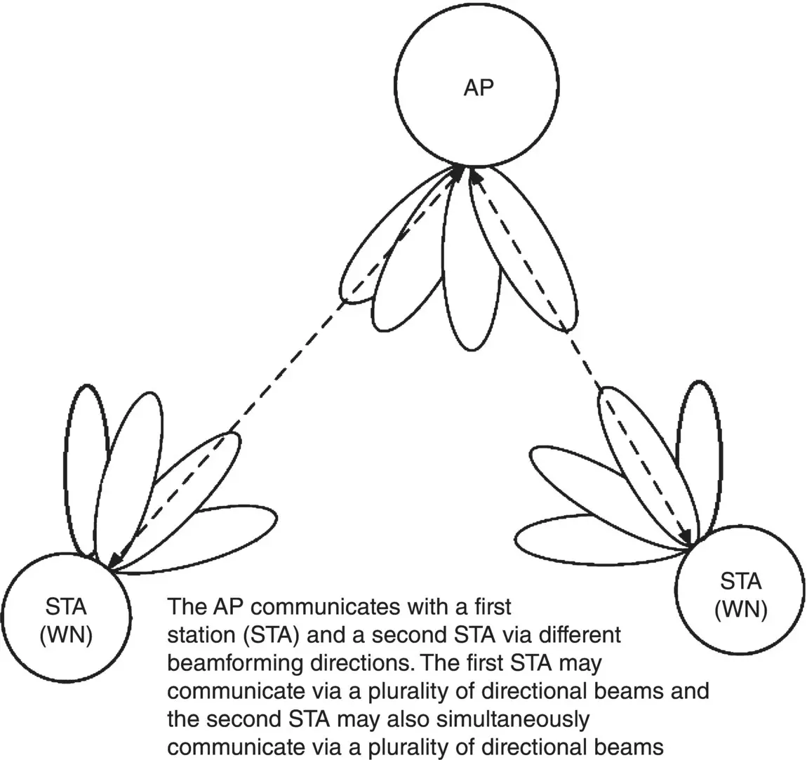
FIGURE 2.7 Distributed MIMO communication with beamforming [20].
The 802.11n standard introduced MIMO to the LAN environment, allowing a maximum of four MIMO streams to be transmitted to a WN at a time; 802.11ac increased the maximum (theoretical) number of single‐user MIMO streams received by a WN to eight, effectively doubling the network throughput with 802.11ac compared to 802.11n (note that 802.11ac MU‐MIMO specification defines radio configurations that support up to four simultaneous MIMO channels 5 ).
Specifically, 802.11ac supports MU‐MIMO affording a major improvement over SU‐MIMO (also just called MIMO). See Figure 2.8. This capability is supported in the DL, and the process is known more specifically as DL‐MU‐MIMO. APs typically have four antennas (APs with eight antennas are also available), but most of the client devices are limited to 1–2 antennas; thus, in a SU‐MIMO channel operation, and the full capacity is rarely achieved. For example, a 4 × 4 Wi‐Fi 11ac AP supports a peak PHY rate of 1.7 Gbps. But a smartphone or tablet with one antenna can only support a peak rate of 433 Mbps, leaving 1.3 Gbps capacity of the AP unused – this difference is called the MIMO gap. 802.11ac addresses the MU‐MIMO gap, allowing an AP to support up to four simultaneous full‐rate Wi‐Fi connections (say, 433 Mbps each) where each of these connections is assigned to a different client device such as smartphone, laptop, or tablet. The total bandwidth of 1.7 Gbps is utilized, representing the systems' bandwidth. In this manner, MU‐MIMO improves performance by affording the AP more options to support the BSS clients and enabling the AP to make full use of the total system throughput. In summary, MU‐MIMO provides increased throughput and reduced latency: the efficient use of available spectrum increases the total capacity of a network by a factor of 2×–3×, and since client devices do not time‐share connections with other clients on the network, each device incurs reduced wait time. To achieve the full MU‐MIMO benefit with an 8 × 8 AP would require an 8 × 8 client configuration; unfortunately, this is not practical, especially with mobile devices and limited battery power (typical mobile clients support 1 × 1 or 2 × 2 configuration). The maximum throughputs in the 5 GHz band are:
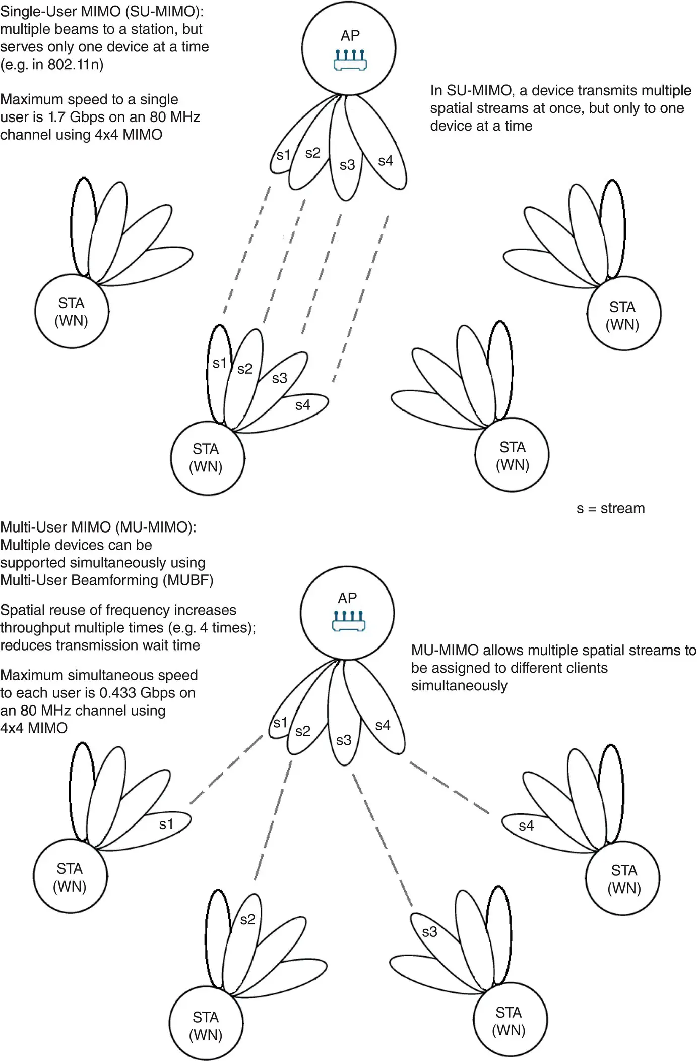
FIGURE 2.8 SU‐MIMO versus MU‐MIMO.
4 × 4/4‐stream: 1.733 Gbps max rate
3 × 3/3‐stream: 1.300 Gbps max rate
2‐stream 802.11ac: 0.867 Gbps max rate
1‐stream 802.11ac: 0.433 Gbps max rate
As noted, in 802.11ac, only a single‐user WN is allowed to transmit (in the UL direction) at a point in time; multiuser DL transmission from an AP to non‐AP WNs is supported through DL‐MU‐MIMO beamforming. The more WNs active in the network, the longer the stations may need to wait before they are allowed to transmit UL a buffered frame. The issue is improved in the 802.11ax specification.
2.5.2 Beamforming
Beamforming is a methodology that focuses the AP's transmit energy of the spatial stream toward the targeted WN. Channel estimation is employed to introduce a small difference in the phase and amplitude in the transmitted signal (a process called precoding) to enable the AP to focus the signal in the direction of the receiving WN. 802.11n had previously defined a number of methods of beamforming, and consequently, chipset vendors implemented various non‐interoperable techniques, keeping beamforming from general acceptance. To address the issue, the 802.11ac specification defined a single closed‐loop SU/MU Transmit Beamforming (TxBF) method where the AP transmits a “special sounding signal” to all WNs – each WN estimates the channel and reports its channel feedback information back to the AP. In the sounding mechanisms, each WN provides channel feedback, which the AP uses to give its spatial streams the necessary mobility. Once channel probing request to the WN results in the WN providing the AP with a characterization of its environment, the AP uses MU‐MIMO beam‐shaping capabilities to maximize signal in the desired direction and squelch the signal in the undesired direction. MU‐MIMO capitalizes on the transmit beamforming capabilities to establish up to four simultaneous directional RF links: this technique provides each of the four users with its own dedicated full‐bandwidth channel. In practice, however, the beamforming process is imperfect, and some of the energy of a spatial stream appears in sidelobes for several degrees off‐axis. Two adjacent MU‐MIMO streams start to interfere with each other as soon as their sidelobes begin to overlap. The presence of this interference adds to the overall noise floor of the channel at the AP. Analysis shows that adding additional MU spatial stream adds intra‐stream interference but increases the number of usable spatial streams; this requires a design tradeoff analysis for specific environments and applications [21].
Читать дальшеИнтервал:
Закладка:
Похожие книги на «High-Density and De-Densified Smart Campus Communications»
Представляем Вашему вниманию похожие книги на «High-Density and De-Densified Smart Campus Communications» списком для выбора. Мы отобрали схожую по названию и смыслу литературу в надежде предоставить читателям больше вариантов отыскать новые, интересные, ещё непрочитанные произведения.


Обсуждение, отзывы о книге «High-Density and De-Densified Smart Campus Communications» и просто собственные мнения читателей. Оставьте ваши комментарии, напишите, что Вы думаете о произведении, его смысле или главных героях. Укажите что конкретно понравилось, а что нет, и почему Вы так считаете.