Daniel Minoli - High-Density and De-Densified Smart Campus Communications
Здесь есть возможность читать онлайн «Daniel Minoli - High-Density and De-Densified Smart Campus Communications» — ознакомительный отрывок электронной книги совершенно бесплатно, а после прочтения отрывка купить полную версию. В некоторых случаях можно слушать аудио, скачать через торрент в формате fb2 и присутствует краткое содержание. Жанр: unrecognised, на английском языке. Описание произведения, (предисловие) а так же отзывы посетителей доступны на портале библиотеки ЛибКат.

- Название:High-Density and De-Densified Smart Campus Communications
- Автор:
- Жанр:
- Год:неизвестен
- ISBN:нет данных
- Рейтинг книги:3 / 5. Голосов: 1
-
Избранное:Добавить в избранное
- Отзывы:
-
Ваша оценка:
High-Density and De-Densified Smart Campus Communications: краткое содержание, описание и аннотация
Предлагаем к чтению аннотацию, описание, краткое содержание или предисловие (зависит от того, что написал сам автор книги «High-Density and De-Densified Smart Campus Communications»). Если вы не нашли необходимую информацию о книге — напишите в комментариях, мы постараемся отыскать её.
The book includes information about security requirements, large and boutique solution providers, applications, unbundled services, implementation planning and design, as well as operations and network management. An epilogue written by Josie Jo-Anne Dressendofer of Slice Wireless concludes the text. Readers will also benefit from the inclusion of:
A thorough introduction to background and functional requirements for high density communications, including requirements for airports, stadiums, convention centers, classrooms, train and subway stations, and smart cities An exploration of traditional voice and cellular technology, including DAS designs and architectures and microcellularization Practical discussions of traditional data and Wi-Fi, including throughput/interference and security A treatment of evolved hotspot connectivity, including Wi-Fi and 5G Perfect for telecommunication researchers and engineers, networking professionals, technology professionals, campus administrators, and equipment vendors,
will also earn a place in the libraries of senior undergraduate and graduate students in applied communications technologies.
High-Density and De-Densified Smart Campus Communications — читать онлайн ознакомительный отрывок
Ниже представлен текст книги, разбитый по страницам. Система сохранения места последней прочитанной страницы, позволяет с удобством читать онлайн бесплатно книгу «High-Density and De-Densified Smart Campus Communications», без необходимости каждый раз заново искать на чём Вы остановились. Поставьте закладку, и сможете в любой момент перейти на страницу, на которой закончили чтение.
Интервал:
Закладка:
Each of the stations and the AP includes a processor and a transceiver and may further include a user interface and a display device. The processor is configured to generate frames to be transmitted through the wireless network, to process frames received through the wireless network, and to execute protocols of the WLAN. The processor performs some or all its functions by executing computer programming instructions stored on a non‐transitory computer‐readable medium. The transceiver represents a unit that is functionally connected to the processor and designed to transmit and receive frames through the wireless network. The transceiver may be defined using a single component that performs the functions of transmitting and receiving, or two separate components, each performing one of such functions [2]. As noted earlier, a station may typically include a desktop computer, a laptop computer, a tablet PC, a wireless phone, a mobile phone, a smartphone, an e‐book reader, a Portable Multimedia Player, a portable game console, a navigation system, a digital camera, and so on.

FIGURE 2.2 Block diagram of a WLAN device (example).
WLAN devices are being deployed in diverse environments; these environments are characterized by the existence of many APs and non‐AP stations in geographically limited areas; increased interference from neighboring devices gives rise to performance degradation. Furthermore, WLAN devices are increasingly required to support a variety of applications such as video, cloud access, and cellular network offloading. In particular, video traffic is expected to be a major, if not the dominant type of traffic in many high‐efficiency WLAN deployments. With the real‐time requirements of some of these applications, WLAN users require improved performance in delivering their applications, including improved power consumption for battery‐operated devices [2].
Some of the PHY techniques are discussed first, followed by a discussion of the Data Link layer techniques.
2.3.1 PHY Layer Operation
Traditionally, at the PHY level, the 802.11 protocol uses a Carrier Sense Multiple Access (CSMA)/Collision Avoidance (CA) channel management method: WNs first sense the channel and endeavor to avoid collisions by transmitting a packet only when they sense the channel to be idle; if the WN detects the transmission of another node, it waits for a random amount of time for that other WN to stop transmitting before sensing again to assess if the channel is free. The process is based on the AP or the WN establishing signal detection energy on a given channel; specifically, the Received Signal Strength Index (RSSI) of the received PLCP (Physical Layer Convergence Protocol) Protocol Data Unit (PPDU) 4 : if the signal detection energy is less than a Clear Channel Assessment (CCA) threshold, the AP or the WN then contends for the channel and transmits its data.
As described, a terminal in a WLAN checks whether a channel is busy or not by performing carrier/channel sensing before transmitting data. Such a process is referred to as CCA , and a signal level used to decide whether the corresponding signal is sensed, is referred to as a CCA threshold . When a radio signal is received by a terminal, it is processed to determine if it has a value exceeding the CCA threshold. When a radio signal having a predetermined or higher‐strength value is sensed, it is determined that the channel under consideration is physically busy, and the terminal delays its access to that channel. When a radio signal is not sensed in the channel under consideration or a radio signal is sensed having a strength smaller than the CCA, then the terminal determines that the channel is idle.
At the PHY layer, the data frame exchanges in WLANs could be performed with a single‐antenna transmission or multiple‐antenna transmission (MIMO techniques). In general, a MIMO communication system employs multiple (N T) transmit antennas and multiple (N R) receive antennas. A MIMO channel formed by the N Ttransmit and N Rreceive antennas may be decomposed into N Sindependent channels, with N S≤ min {N T,N R}. Each of the N Sindependent channels is also referred to as a spatial subchannel or eigenmode of the MIMO channel. In some environments, MIMO exploits multipath propagation. MU‐MIMO is an evolution from the single‐user MIMO technology. In WLAN applications, MIMO methods allow the APs and STAs to increase the number of antennas for both transmitting and receiving, thus improving the system capacity for wireless connections. MIMO methods are utilized in IEEE 802.11n, IEEE 802.11ac, and IEEE 802.11ax; they are also used in Evolved High Speed Packet Access (HSPA+)/3G cellular, Long Term Evolution (LTE)/4G cellular, 5G cellular, and WiMAX. Older WLAN standards, such as 802.11b, 802.11g, and 802.11n, do not support MU‐MIMO. Initially, only routers and APs supported the technology; now, many endpoint devices support MU‐MIMO (including smartphones) support 802.11ac MU‐MIMO technology. Figure 2.3depicts a general MU‐MIMO system.
In the case of a multiple‐antenna, or MIMO transmission, multiple spatial streams (SS) are sent within the same frame from one station or AP, which usually is called a beamformer (BFer), to another station or AP, which is usually called a beamformee (BFee); this type of transmission is called beamforming (BF) transmission. BF and MIMO transmissions are usually enhanced by some initial frame exchanges so that the BFer knows about the MIMO channel conditions. This initial exchange of frames before the actual data frame exchange is called a sounding procedure. The frames that might be used in a sounding procedure are (i) the HT and very high throughput (VHT) Null Data Packet (NDP) frames, (ii) the VHT MIMO Compressed Beamforming Report frame, (iii) the VHT NDP Announcement (NDPA) frame, and (iv) the VHT Beamforming Report Poll frame. Each of these frames may have various fields and subfields such as: VHT MIMO Control, VHT Compressed Beamforming Report, MU Exclusive Beamforming Report, Sounding Dialog Token, STA Info, and related fields that are utilized for exchanging information relevant to beamforming [4].
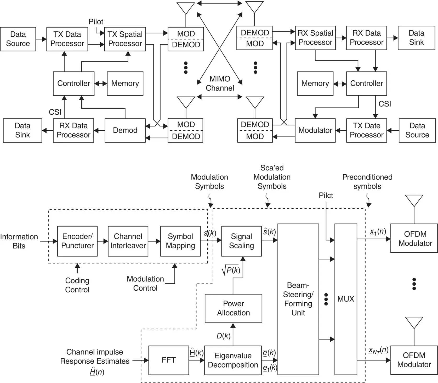
FIGURE 2.3 A general MIMO system (after [12]).
In 802.11ac standards, MU‐MIMO is employed for the downlink (DL). MU‐MIMO is a technology that enables a plurality of signals to be transmitted in the same time slot by space division multiplexing; with this technology, it is possible to improve utilization efficiency of the spectrum [13]. MU‐MIMO is used in WLANs to support congested environments where many users are trying to access the wireless network at the same time. When multiple users (e.g. smartphones, tablets, computers) begin accessing the AP simultaneously, or practically simultaneously, congestion can arise as the AP services the first user's request, while the second (and subsequent) users are forced to wait. MU‐MIMO mitigates this situation by allowing multiple users to access AP functions, thus reducing congestion. MU‐MIMO systems segment the available bandwidth into separate, discrete streams that share the connection equally. An MU‐MIMO AP may have 2 × 2, 3 × 3, 4 × 4, or 8 × 8 variations, where the designation refers to the number of streams (two, three, four, or eight) that are created by the AP. To obtain the desired improvements, the AP must enable MU‐MIMO and beamforming functionality. The streams are spatial in nature; while interference is minimized if two devices are in proximity to each other, they still share the same stream. Prior to 802.11ax, the MU‐MIMO procedure only applies to DL connections; this may be fine for home users that need faster downloading speeds for 4K video content, but it is less useful for business users who need faster uploads for two‐way high‐quality video conferencing applications [14]. IEEE 802.11ax supports bidirectional MU‐MIMO. In addition to allowing 8 × 8 arrays, the 802.11ax standard addresses the use of uplink (UL) MU‐MIMO.
Читать дальшеИнтервал:
Закладка:
Похожие книги на «High-Density and De-Densified Smart Campus Communications»
Представляем Вашему вниманию похожие книги на «High-Density and De-Densified Smart Campus Communications» списком для выбора. Мы отобрали схожую по названию и смыслу литературу в надежде предоставить читателям больше вариантов отыскать новые, интересные, ещё непрочитанные произведения.


Обсуждение, отзывы о книге «High-Density and De-Densified Smart Campus Communications» и просто собственные мнения читателей. Оставьте ваши комментарии, напишите, что Вы думаете о произведении, его смысле или главных героях. Укажите что конкретно понравилось, а что нет, и почему Вы так считаете.