Kalyan K. Sen - Power Flow Control Solutions for a Modern Grid Using SMART Power Flow Controllers
Здесь есть возможность читать онлайн «Kalyan K. Sen - Power Flow Control Solutions for a Modern Grid Using SMART Power Flow Controllers» — ознакомительный отрывок электронной книги совершенно бесплатно, а после прочтения отрывка купить полную версию. В некоторых случаях можно слушать аудио, скачать через торрент в формате fb2 и присутствует краткое содержание. Жанр: unrecognised, на английском языке. Описание произведения, (предисловие) а так же отзывы посетителей доступны на портале библиотеки ЛибКат.
- Название:Power Flow Control Solutions for a Modern Grid Using SMART Power Flow Controllers
- Автор:
- Жанр:
- Год:неизвестен
- ISBN:нет данных
- Рейтинг книги:5 / 5. Голосов: 1
-
Избранное:Добавить в избранное
- Отзывы:
-
Ваша оценка:
Power Flow Control Solutions for a Modern Grid Using SMART Power Flow Controllers: краткое содержание, описание и аннотация
Предлагаем к чтению аннотацию, описание, краткое содержание или предисловие (зависит от того, что написал сам автор книги «Power Flow Control Solutions for a Modern Grid Using SMART Power Flow Controllers»). Если вы не нашли необходимую информацию о книге — напишите в комментариях, мы постараемся отыскать её.
Power Flow Control Solutions for a Modern Grid using SMART Power Flow Controllers
Power Flow Control Solutions for a Modern Grid using SMART Power Flow Controllers
Power Flow Control Solutions for a Modern Grid Using SMART Power Flow Controllers — читать онлайн ознакомительный отрывок
Ниже представлен текст книги, разбитый по страницам. Система сохранения места последней прочитанной страницы, позволяет с удобством читать онлайн бесплатно книгу «Power Flow Control Solutions for a Modern Grid Using SMART Power Flow Controllers», без необходимости каждый раз заново искать на чём Вы остановились. Поставьте закладку, и сможете в любой момент перейти на страницу, на которой закончили чтение.
Интервал:
Закладка:
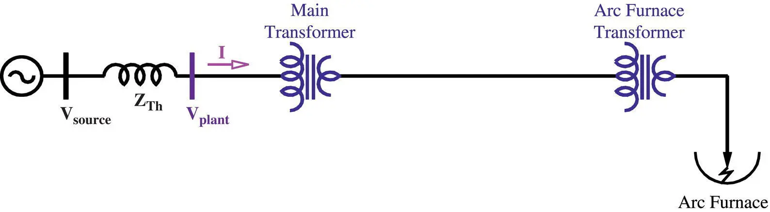
Figure 1-15 A single‐line diagram of an electric arc furnace.
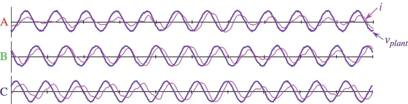
Figure 1-16 Instantaneous plant input bus voltage ( v plant) and plant current ( i ), drawn by a typical electric arc furnace (field performance) (Sen 2015).
A typical instantaneous plant input bus voltage ( v plant) and current ( i ), drawn by an electric arc furnace in three phases (A, B, and C) without any compensation, are shown in Figure 1-16. During the operation of the arc furnace, the random nature of the load current ( i.e . electric arc) creates proportionally rapid and random voltage changes across Z Th. When this random voltage across Z This subtracted from the regulated source voltage ( V source), a varying voltage, known as voltage flicker, is created at the input voltage bus of the plant. However, the fast‐acting STATCOM is capable of providing a unique solution to reduce this voltage flicker by supplying the fluctuating active power ( Figure 1-19) and reactive power ( Figure 1-18) needs of the rapidly‐changing load of the electric arc furnace. Since a typical load is more inductive than capacitive in nature, the compensation scheme is designed to be more capacitive than inductive in nature. Since STATCOM operates both in capacitive and inductive modes in near‐equal ranges, a STATCOM, combined with an optional Fixed Capacitor (FC) may be an appropriate solution in this application. In 1998, Westinghouse installed a +140/–20‐MVA‐rated power electronics VSC‐based shunt compensator, consisting of a ±80‐MVA‐rated STATCOM and a +60‐MVA‐rated FC at a steel plant as shown in Figure 1-17.
The voltage ( V comp) at the compensation bus is regulated to maintain the voltage flicker at an acceptable level. The control philosophy in this project is given by the following equations:
(1‐6) 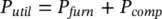
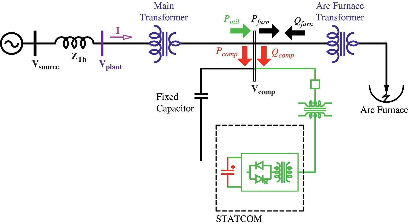
Figure 1-17 Use of a STATCOM, combined with a Fixed Capacitor (FC) as an arc furnace compensator.
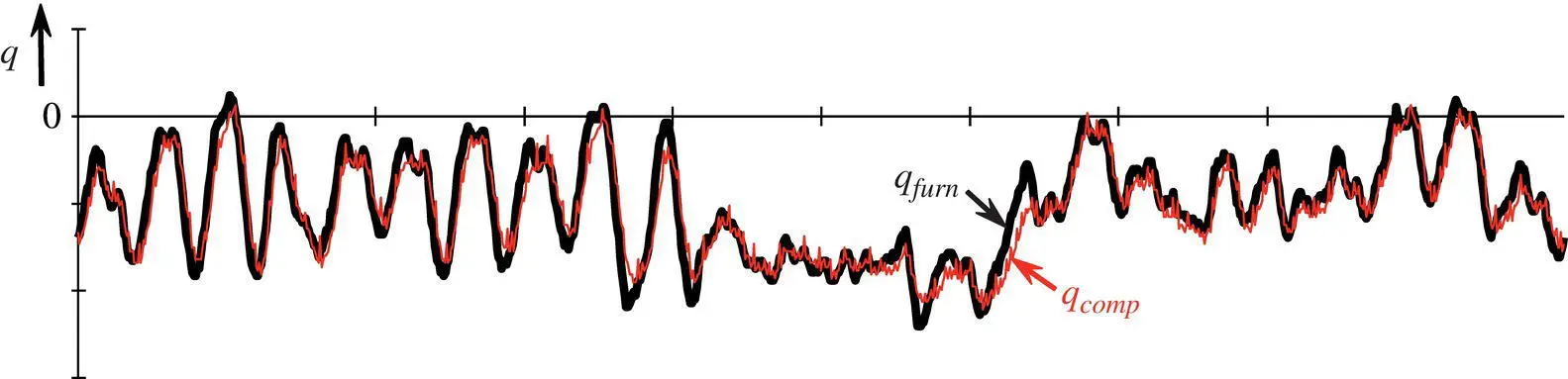
Figure 1-18 Instantaneous reactive power drawn by the furnace and supplied by the compensator (STATCOM and FC) (field performance) (Sen 2015).
where
Putil is the active power supplied by the utility
Pfurn is the active power used by the arc furnace
Pcomp is the active power exchanged by the compensator
and
(1‐7) 
where
Qfurn is the reactive power used by the arc furnace
Qcomp is the reactive power exchanged by the compensator.
As shown in Figure 1-18, the compensation scheme supplies nearly all the instantaneous reactive power ( q ) drawn by the furnace.
This preferred solution for a utility application is to use a larger‐than‐usual‐sized DC capacitor, which provides a sink and a source of fluctuating active power for the load, thereby leveling off the active power drawn from the utility source. The instantaneous active power ( p ) drawn by the compensator, which is composed of a STATCOM and a FC, and the furnace and supplied by the utility are shown in Figure 1-19. The negative active power drawn by the compensator indicates that a part of the furnace power is supplied by the compensator. If the size of the DC capacitor was further increased to support a larger amount of fluctuating active power, the active power drawn from the utility could be made equivalent to a fixed resistive load.
A comparison of voltage flicker (termed as Level) without and with a compensation, provided by the STATCOM and the FC, is shown in Figure 1-20. The flicker measurements without and with a compensation show that the STATCOM was designed correctly to reduce the flicker to a desired level of below 0.25% at 75 MW of load. Therefore, it was not commercially needed to increase the size of the DC capacitor any further. Even though this is the most useful application of a VSC‐based STATCOM, it was also retired from service due to component obsolescence within a few years after commissioning and a less perfect, but adequate solution – naturally commutated, thyristor‐based SVC was installed in its place.
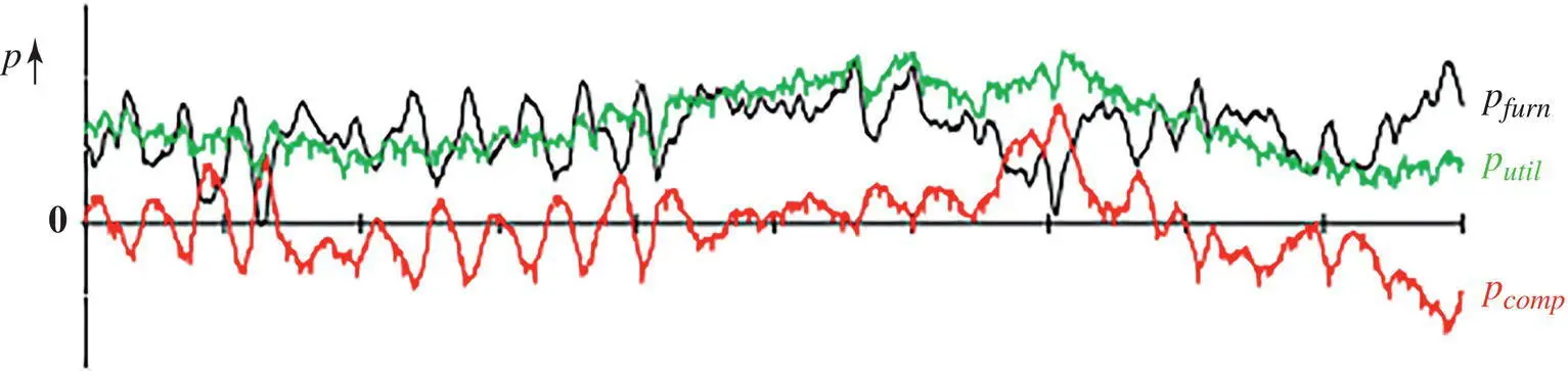
Figure 1-19 Instantaneous active power drawn by a compensator (STATCOM and FC) and a furnace and supplied by a utility (field performance) (Sen 2015).
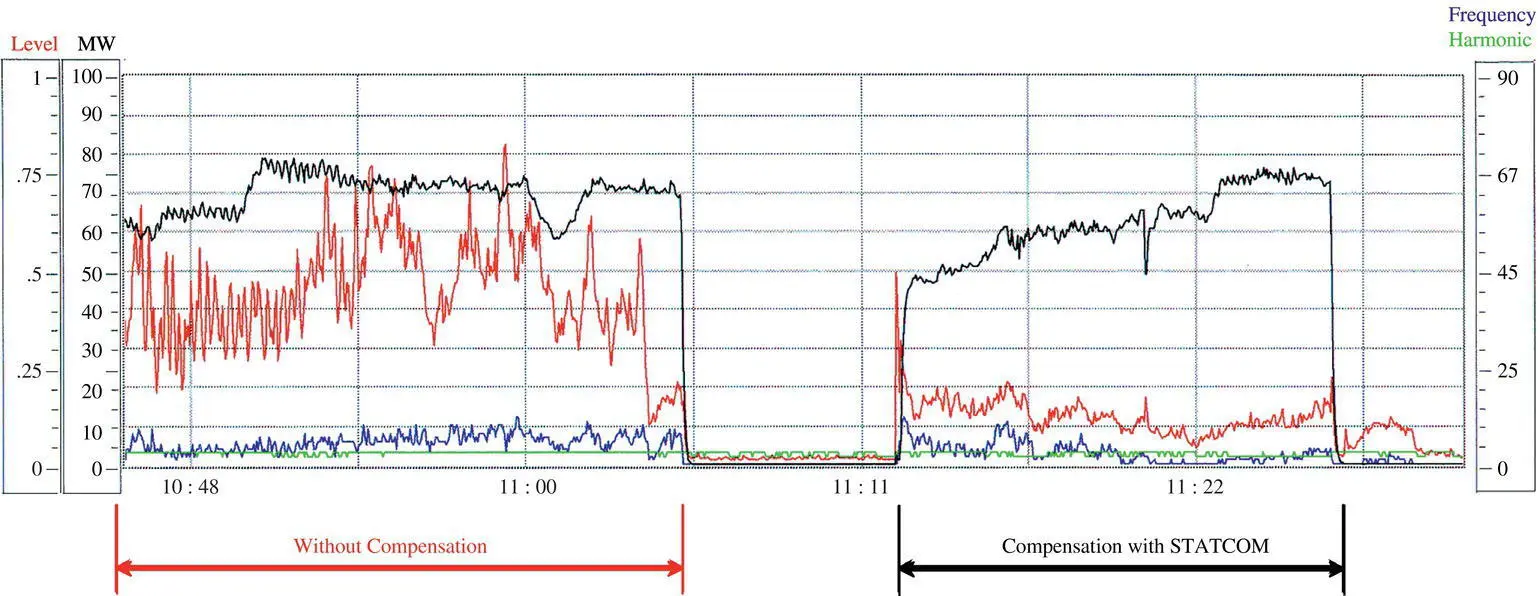
Figure 1-20 Flicker measurements without and with a compensation provided by a STATCOM (field performance) (Sen 2015).
The first generation of FACTS Controllers consisted of GTO‐based VSCs. Since the commissioning of the world’s first commercial STATCON at TVA in 1995, nine GTO‐based VSCs were built. During the same time, several IGBT‐based VSCs were also built. During the past two decades, the IGBT technology has advanced by several generations. So, what about the GTO technology? Unfortunately, it is no longer manufactured. While the IGBT is the industry workhorse at the present time, the future trend is to develop wide bandgap‐type Silicon Carbide (SiC)‐ and Gallium Nitride (GaN)‐based switches due to the several attractive attributes: higher‐temperature operation, smaller turn‐on and turn‐off times that result in a lower switching loss, smaller gate‐drive circuit, smaller snubber circuit, lower cooling requirement, and so on. So how can one source spare parts for the GTO‐based FACTS Controllers? That is not an easy question to answer. Most of the installations with GTO‐based VSCs were dismantled after a short life span, which was unforeseen at the inception of FACTS development. Based on the facts about FACTS Controllers of the last three decades, component obsolescence is the primary reason for a 10–15 years of life span of power electronics‐based VSCs.
In this context, one might ask why not use the latest high‐power electronics switches to replace the aging outdated switches? The answer is simple – it is impossible. Even though there is no available switch, which can be considered as a perfect switch, meaning zero forward voltage across the switch during conduction and zero transition time from on‐to‐off and vice versa, the snubber circuit, gate‐drive circuit, and cooling requirement vary from a VSC that is made with one type of switch to another VSC that is made with a different type of switch. This fact alone forces the aging VSCs to retire when spare parts are unavailable.
Читать дальшеИнтервал:
Закладка:
Похожие книги на «Power Flow Control Solutions for a Modern Grid Using SMART Power Flow Controllers»
Представляем Вашему вниманию похожие книги на «Power Flow Control Solutions for a Modern Grid Using SMART Power Flow Controllers» списком для выбора. Мы отобрали схожую по названию и смыслу литературу в надежде предоставить читателям больше вариантов отыскать новые, интересные, ещё непрочитанные произведения.


Обсуждение, отзывы о книге «Power Flow Control Solutions for a Modern Grid Using SMART Power Flow Controllers» и просто собственные мнения читателей. Оставьте ваши комментарии, напишите, что Вы думаете о произведении, его смысле или главных героях. Укажите что конкретно понравилось, а что нет, и почему Вы так считаете.