John III Beumer - Fundamentals of Implant Dentistry
Здесь есть возможность читать онлайн «John III Beumer - Fundamentals of Implant Dentistry» — ознакомительный отрывок электронной книги совершенно бесплатно, а после прочтения отрывка купить полную версию. В некоторых случаях можно слушать аудио, скачать через торрент в формате fb2 и присутствует краткое содержание. Жанр: unrecognised, на английском языке. Описание произведения, (предисловие) а так же отзывы посетителей доступны на портале библиотеки ЛибКат.
- Название:Fundamentals of Implant Dentistry
- Автор:
- Жанр:
- Год:неизвестен
- ISBN:нет данных
- Рейтинг книги:5 / 5. Голосов: 1
-
Избранное:Добавить в избранное
- Отзывы:
-
Ваша оценка:
Fundamentals of Implant Dentistry: краткое содержание, описание и аннотация
Предлагаем к чтению аннотацию, описание, краткое содержание или предисловие (зависит от того, что написал сам автор книги «Fundamentals of Implant Dentistry»). Если вы не нашли необходимую информацию о книге — напишите в комментариях, мы постараемся отыскать её.
Fundamentals of Implant Dentistry — читать онлайн ознакомительный отрывок
Ниже представлен текст книги, разбитый по страницам. Система сохранения места последней прочитанной страницы, позволяет с удобством читать онлайн бесплатно книгу «Fundamentals of Implant Dentistry», без необходимости каждый раз заново искать на чём Вы остановились. Поставьте закладку, и сможете в любой момент перейти на страницу, на которой закончили чтение.
Интервал:
Закладка:
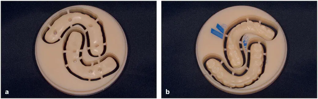
Fig 5-5 (a and b) Provisional full-arch prosthesis milled of PMMA. Pucks are available in other materials such as cobalt-chromium, titanium, and zirconia.
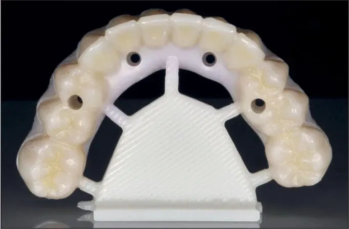
Fig 5-6 Fully sintered monolithic zirconia prosthesis.
History and Technologic Background
Role of Moore’s law on development of intraoral scanners and digital dentistry
Since the initial description of dental laser holography in the 1970s 20and the first commercial intraoral scanner (IOS) in the 1980s, 21, 22many optical imaging technologies have been developed for dentistry. This competition has resulted in numerous affordable scanners that are constantly improving in accuracy, speed, ease of use, and compatibility with multiple design softwares, mills, and printers. Furthermore, IOSs are adding features beyond surface mapping, such as full-color capturing, shade matching, and caries detection. In fact, the current generation of IOSs are vastly better than the previous generation from only 5 years ago in most measurable performance criteria that matter to the clinician. Along with the emergence of powerful CAD software, advances in milling machines and 3D printers, availability of advanced materials, and global adoption of the internet, IOSs have played a key role in the evolution of digital dentistry. In many ways, these major trends have benefited either directly or indirectly from the drastic decrease in the cost for computational power over this time period. In the 1980s, one dollar would purchase enough computational power to perform ten million standard operations per second. Today, the same inflation-adjusted dollar would purchase ten million times more computing power. Over this period, this so-called “price-performance Moore’s law” has resulted in a tenfold increase in computational power per dollar every 4 years. The fact that today’s smartphones and tablets are faster than the fastest workstations in the 1980s has fundamentally changed the IOS engineer’s toolbox. Along with high- performance video cards built for the gaming industry, the new generation of IOSs are able to incorporate technologies involving multiwavelength, structured light sources, moving mirrors, and innovative temporal-spatial patterns to reconstruct accurate 3D models in real time. These require increasingly sophisticated, computationally demanding, mathematical reconstruction algorithms. The reliance on raw computational power by IOSs will only increase, and many systems will require high-end gaming computers to capture, render, and display the 3D images properly as the systems continue to improve over the next 5 years.
Computed tomography
One of the early advancements in digital technology, and perhaps the most important for implant dentistry, was the ability to visualize radiographic images in 3D. In the past, periapical or panoramic radiographs were considered the standard by which we based much of our diagnostic information. The limitation of 2D analyses led to much variation in assessing anatomical landmarks and the placement of implants. Computed tomography (CT) used in medical imaging introduced the dental field to 3D analyses, thereby significantly enhancing our diagnostic abilities and allowing better visualization of the potential implant sites prior to implant placement. The negative aspects of this technology were the cost of the CT scan and the radiation dose delivered to the patient. Subsequently, dental CBCT has been developed specifically for the dental field, which is based on producing divergent x-ray beams that form a cone. The CBCT unit is smaller in size than the CT, making their use ideal for the dental office. Over the last few years, CBCT has become very popular due to the recent advances in low-dose CBCT, the availability of compact CBCT units, and the availability of user-friendly software. As CBCT scanning technology has improved, it has allowed the clinician to differentiate between hard and soft tissue structures to a much greater degree (see Fig 5-7). 23Because a CBCT image clearly outlines the vital anatomical features such as the inferior alveolar nerve, the number, size, angulation, and depth of the implant can be planned virtually. Further, the individual sites for implant placement can be evaluated for adequate bone, and some software programs can evaluate soft tissue volume as well as whether the sites require augmentation prior to or during implant surgery ( Figs 5-7and 5-8).
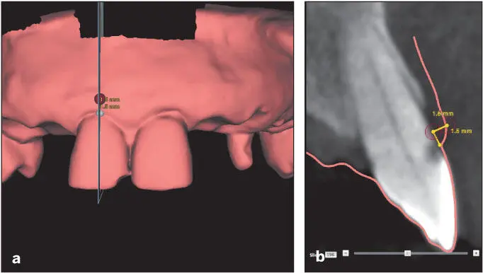
Fig 5-7 (a and b) This CBCT evaluation allows visualization of the overlying soft tissues and indicates that the gingival tissues are relatively thin. The soft tissue contours and thickness are visible due to the combining of the DICOM files (showing hard tissue) and STL files (showing soft tissue). Accordingly, extra precautions should be taken when this tooth is removed in preparation for implant placement (Reprinted from Moy et al 23with permission.)
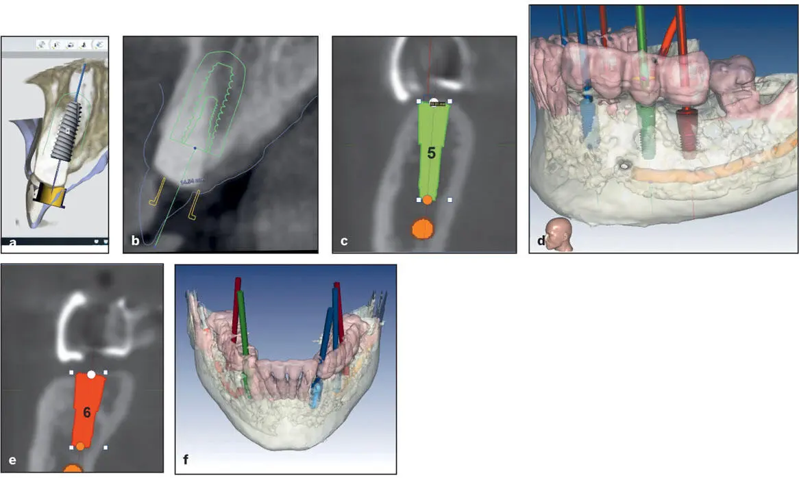
Fig 5-8 Virtual planning for immediate implant positioning. (a and b) In the esthetic zone, angulation and position are critical to achieving appropriate esthetic outcomes that will sustain the bone and soft tissues over the long term. Note that the implant is positioned such that the abutment screw channel exits in the cingulum area. (c to f) For posterior quadrants, visualizing vital structures, such as the inferior alveolar nerve and lingual concavity of the mandible, is mandatory. Lateral views are available to determine buccal extent and ensure there is sufficient thickness of bone circumscribing the implants with the chosen positions. Implant positions and angulations can be verified in both 2D and 3D. Note that these implants have been positioned consistent with the application of occlusal forces along their long axis with respect to the curve of Spee and curve of Wilson.
Although the CBCT scan is less accurate than the CT scan, the advantages of the CBCT scan over the CT scan are the radiation exposure is significantly less and the scans can be performed in the dental office. Common sources of error include improper positioning of the patient, not obtaining the appropriate anatomical fields/scan volume, movement by the patient during the scan, or scatter due to significant amounts of dental restorations, especially metal-based ones ( Fig 5-9). 23, 24
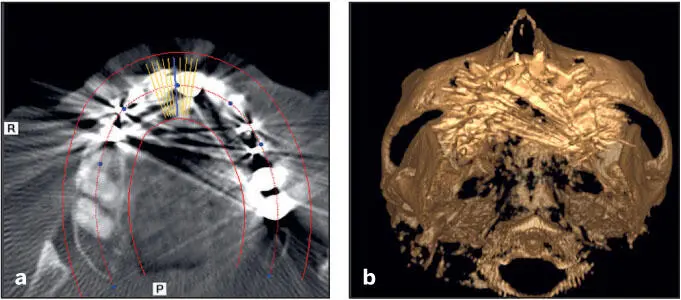
Fig 5-9 (a) Horizontal slice of a CBCT demonstrating scatter from metallic dental restorations. (b) Despite autosegmentation, details of the tooth restoration surfaces are not outlined clearly. This will cause any guide fabricated off these to fit poorly. (Reprinted from Moy et al 23with permission.).
It is crucial to properly undergo segmentation of these images. Although most current softwares may automatically perform this step (fully or partially), poor segmentation of these images can still occur. When the segmentation is not carefully performed, it may lead to errors that are manifested during the operatory phase, such as ill-fitting implant surgical guides ultimately leading to poor implant placements or disuse of the guide intraoperatively. The clinician should therefore be familiar with reviewing the CBCT information and the interpretation of possible distortions and artifacts in the images.
Читать дальшеИнтервал:
Закладка:
Похожие книги на «Fundamentals of Implant Dentistry»
Представляем Вашему вниманию похожие книги на «Fundamentals of Implant Dentistry» списком для выбора. Мы отобрали схожую по названию и смыслу литературу в надежде предоставить читателям больше вариантов отыскать новые, интересные, ещё непрочитанные произведения.


Обсуждение, отзывы о книге «Fundamentals of Implant Dentistry» и просто собственные мнения читателей. Оставьте ваши комментарии, напишите, что Вы думаете о произведении, его смысле или главных героях. Укажите что конкретно понравилось, а что нет, и почему Вы так считаете.