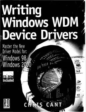
Chris Cant - Writing Windows WDM Device Drivers
Здесь есть возможность читать онлайн «Chris Cant - Writing Windows WDM Device Drivers» весь текст электронной книги совершенно бесплатно (целиком полную версию без сокращений). В некоторых случаях можно слушать аудио, скачать через торрент в формате fb2 и присутствует краткое содержание. Город: Lawrence, Kansas 66046, ISBN: , Издательство: R & D Books, Жанр: Программирование, на английском языке. Описание произведения, (предисловие) а так же отзывы посетителей доступны на портале библиотеки ЛибКат.
- Название:Writing Windows WDM Device Drivers
- Автор:
- Издательство:R & D Books
- Жанр:
- Год:неизвестен
- Город:Lawrence, Kansas 66046
- ISBN:0-87930-565-7
- Рейтинг книги:5 / 5. Голосов: 1
-
Избранное:Добавить в избранное
- Отзывы:
-
Ваша оценка:
- 100
- 1
- 2
- 3
- 4
- 5
Writing Windows WDM Device Drivers: краткое содержание, описание и аннотация
Предлагаем к чтению аннотацию, описание, краткое содержание или предисловие (зависит от того, что написал сам автор книги «Writing Windows WDM Device Drivers»). Если вы не нашли необходимую информацию о книге — напишите в комментариях, мы постараемся отыскать её.
Writing Windows WDM Device Drivers — читать онлайн бесплатно полную книгу (весь текст) целиком
Ниже представлен текст книги, разбитый по страницам. Система сохранения места последней прочитанной страницы, позволяет с удобством читать онлайн бесплатно книгу «Writing Windows WDM Device Drivers», без необходимости каждый раз заново искать на чём Вы остановились. Поставьте закладку, и сможете в любой момент перейти на страницу, на которой закончили чтение.
Интервал:
Закладка:
First, three constants are defined to represent the offsets to each register in the parallel port electronics.
The InitPrinter BYTE array stores the commands to initialize the printer. Each line has one command and its parameters. First, the Control port INIT# line is set low by writing 0xC8 using the PHDIO_WRITE command. The PHDIO_DELAY command then waits for 60µs. The INIT# signal is set high. The write value of 0xDC also selects the printer and enables interrupts. A further delay of 60us completes the operation.
The DeviceIoControl Win32 function is used to issue the IOCTL_PHDIO_RUN_CMDS IOCTL. This IOCTL runs the given commands straightaway. The InitPrinter array is passed as the input to the IOCTL. IOCTL_PHDIO_RUN_CMDS can optionally be passed an output buffer.
If there is an output buffer that is big enough, the first two 16-bit words in the output indicate any problems that the WdmIo driver found. The first word is an error code. The second word is the zero-based index into the command buffer in which the problem was found. Both are zero if there were no problems. The possible error codes are also found in Ioctl.h in the WdmIo\Sys directory.
The WdmIoTest code rather sloppily does not bother to check the returned error code. If using this driver for real, make sure that you check all error codes.
Listing 15.1 WdmIo Test issuing commands to run straightaway
const BYTE PARPORT_DATA = 0;
const BYTE PARPORT_STATUS = 1;
const BYTE PARPORT_CONTROL = 2;
BYTE InitPrinter[] = {
PHDIO_WRITE, PARPORT_CONTROL, 0xC8, // Take INIT# low
PHDIO_DELAY, 60, // Delay 60us
PHDIO_WRITE, PARPORT_CONTROL, 0xDC, // INIT# high, select printer,
// enable interrupts
PHDIO_DELAY, 60, // Delay 60us
};
int main(int argc, char* argv[]) {
// …
DWORD BytesReturned;
WORD rv[3];
if (DeviceIoControl(hWdmIo, IOCTL_PHDIO_RUN_CMDS,
InitPrinter, length(InitPrinter), // Input
rv, sizeof(rv), // Output
&BytesReturned, NULL)) {
printf(" InitPrinter OK. rv=%d at %d\n", rv[0], rv[13);
} else {
printf("XXX InitPrinter failed %d\n",GetLastError());
goto fail;
}
// …
Reading Data
If you use the PHDIO_READ or PHDIO_READS commands, you must provide an output buffer that is big enough to receive the read data. Remember that the first four bytes of the output buffer are always used for the error code and location.
Listing 15.2 shows how the ReadStatus commands are issued. It simply reads a byte value from the Status port. After DeviceIoControl has returned, the fifth byte of the output buffer contains the Status register contents. WdmIoTest checks that the BUSY# and ONLINE signals are 1 before continuing.
Listing 15.2 Reading data
BYTE ReadStatus[] = {
PHDIO_READ, PARPORT_STATUS, // Read status
};
int main(int argc, char* argv[]) { //…
DWORD BytesReturned;
WORD rv[3];
if (DeviceIoControl(hWdmIo, IOCTL_PHDIO_RUN_CMDS,
ReadStatus, length(ReadStatus), // Input
rv, sizeof(rv), // Output
&BytesReturned, NULL)) {
PBYTE pbrv = (PBYTE)&rv[2];
printf(" ReadStatus OK. rv=%d at %d status=%02X\n", rv[0], rv[l], *pbrv);
if ( (*pbrv&0x88)==0x88) {
busy = false;
break;
}
}
The WriteFile Win32 call is used to pass output data to the WdmIo driver. However, it needs to know how to process the data and handle interrupts. Two steps are required before WriteFile is called. First, connect to the interrupt. Second, pass WdmIo a series of commands that it will run to send the first byte and process each write interrupt.
Connecting to an Interrupt
When the WdmIo device is started, it is told which interrupt to use. However, it does not connect to the interrupt (i.e., install its interrupt handler), as it does not yet know how to handle the interrupt.
The ConnectToInterrupts commands shown here are used to initialize WdmIo's interrupt handling. The first write command tells the parallel port hardware not to generate interrupts. The second command tells the WdmIo driver to use a time-out of 10 seconds when processing subsequent WriteFile (and ReadFile ) requests. WdmIo must have a time-out; a default of 10 seconds is used if no PHDIO_TIMEOUT command is given.
BYTE ConnectToInterrupts[] = {
PHDIO_WRITE, PARPORT_CONTROL, 0xCC, // Disable interrupts
PHDICO_TIMEOUT, 10, // Write time-out in seconds
PHDIO_IRQ_CONNECT, PARPORT_STATUS, 0x00, 0x00, // Connect to interrupt
};
The last command, PHDIO_IRQ_CONNECT, connects the WdmIo driver to its interrupt. As mentioned before, the actual interrupt number is passed as a resource when the WdmIo device is started. WdmIo starts servicing a hardware interrupt by reading a hardware register; in this case, the Status register is read. It must determine whether the interrupt was caused by its hardware or not.
The two final parameters to the PHDIO_IRQ_CONNECT command are a mask and a value. The register contents are ANDed with the mask and compared to the value, as shown in the following WdmIo code snippet. If they are not equal, the interrupt must be intended for another driver.
// See if interrupt is ours
UCHAR StatusReg = ReadByte(dx, dx->InterruptReg);
if ((StatusReg&dx->InterruptRegMask) != dx->InterruptRegValue) return FALSE; // Not ours
Suppose the Status register really did reset its bit 2 to 0 when it generated an interrupt. Specifying 0x04, as the mask would isolate bit 2. If the ANDed result is equal to 0x00, the interrupt is ours. Therefore, specifying a PHDIO_IRQ_CONNECT mask of 0x04 and value of 0x00 would have correctly detected when the parallel port interrupted.
However, as stated earlier, I found that there is no interrupt indication in the Status register. I simply have to assume that if an interrupt arrives, it came from the correct parallel port. To persuade the WdmIo code to continue regardless, a mask of 0x00 and a value of 0x00 was specified in the ConnectToInterrupts code.
Storing the Write Byte Commands
The WdmIo driver needs to be told a series of commands that write a single byte of data. These commands are used both to write the first output byte and to process an interrupt to send another byte.
IOCTL_PHDIO_CMDS_FOR_WRITE is used to store the commands used to write data. This IOCTL is issued using DeviceIoControl in the normal way. The commands are in the input buffer. No output buffer need be specified.
Listing 15.3 shows the WriteByte commands that WdmIoTest tells WdmIo to use to write a data byte. The first PHDIO_WRITE command ensures that the STROBE output signal in bit 0 of the Control register is off. The PHDIO_WRITE_NEXT command is used to write the next byte in the output buffer to the Data port. PHDIO_DELAY is used to delay for 1µs while the output signals settle. The STROBE signal is then set. A delay of 1µs is used before turning STROBE off again. A last delay of 1µs is introduced just to be on the safe side. Finally, the Status register is read; I shall show later on how to access this value.
Читать дальшеИнтервал:
Закладка:
Похожие книги на «Writing Windows WDM Device Drivers»
Представляем Вашему вниманию похожие книги на «Writing Windows WDM Device Drivers» списком для выбора. Мы отобрали схожую по названию и смыслу литературу в надежде предоставить читателям больше вариантов отыскать новые, интересные, ещё непрочитанные произведения.
Обсуждение, отзывы о книге «Writing Windows WDM Device Drivers» и просто собственные мнения читателей. Оставьте ваши комментарии, напишите, что Вы думаете о произведении, его смысле или главных героях. Укажите что конкретно понравилось, а что нет, и почему Вы так считаете.


