Тьерри Мейссан - 11 сентября 2001
Здесь есть возможность читать онлайн «Тьерри Мейссан - 11 сентября 2001» весь текст электронной книги совершенно бесплатно (целиком полную версию без сокращений). В некоторых случаях можно слушать аудио, скачать через торрент в формате fb2 и присутствует краткое содержание. Город: Москва, Год выпуска: 2002, Издательство: Карно, Жанр: Публицистика, на русском языке. Описание произведения, (предисловие) а так же отзывы посетителей доступны на портале библиотеки ЛибКат.

- Название:11 сентября 2001
- Автор:
- Издательство:Карно
- Жанр:
- Год:2002
- Город:Москва
- ISBN:нет данных
- Рейтинг книги:5 / 5. Голосов: 1
-
Избранное:Добавить в избранное
- Отзывы:
-
Ваша оценка:
11 сентября 2001: краткое содержание, описание и аннотация
Предлагаем к чтению аннотацию, описание, краткое содержание или предисловие (зависит от того, что написал сам автор книги «11 сентября 2001»). Если вы не нашли необходимую информацию о книге — напишите в комментариях, мы постараемся отыскать её.
марионеточном, характере политической науки в России.
11 сентября 2001 — читать онлайн бесплатно полную книгу (весь текст) целиком
Ниже представлен текст книги, разбитый по страницам. Система сохранения места последней прочитанной страницы, позволяет с удобством читать онлайн бесплатно книгу «11 сентября 2001», без необходимости каждый раз заново искать на чём Вы остановились. Поставьте закладку, и сможете в любой момент перейти на страницу, на которой закончили чтение.
Интервал:
Закладка:
Vierendeel action occurs in rigid trusses that do not have diagonals. In such structures, stiffness is achieved through the flexural (bending) strength of the connected members. In the lower seven stories of the towers, where there were fewer columns (Figure 2-4), vertical diagonal braces were in place at the building cores to provide this stiffness. This structural frame was considered to constitute a tubular system.
Floor construction typically consisted of 4 inches of lightweight concrete on 1-1/2-inch, 22-gauge non-composite steel deck. In the core area, slab thickness was 5 inches. Remember, that it is important for the «official line» that there be a discontinuity between «inside the core» and «outside the core». Hence, the 5 inch slab inside the core and 4 inch slab outside the core. Outside the central core, the floor deck was supported by a series of composite floor trusses that spanned between the central core and exterior wall. I claim that this is nonsense, see the article The World Trade Center Demolition. Composite behavior with the floor slab was achieved by extending the truss diagonals above the top chord so that they would act much like shear studs, as shown in Figure 2-6.
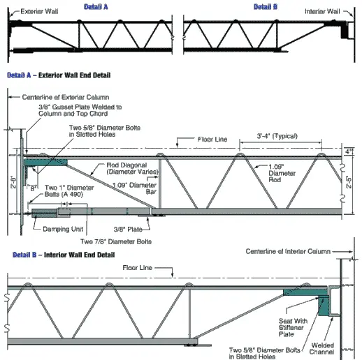
Figure 2-6 Floor truss member with detail of end connections.
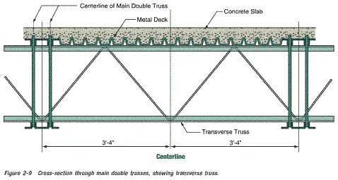
Detailing of these trusses was similar to that employed in open-web joist fabrication and, in fact, the trusses were manufactured by a joist fabricator, the LaClede Steel Corporation. However, the floor system design was not typical of open-web-joist floor systems. It was considerably more redundant and was well braced with transverse members. Trusses were placed in pairs, with a spacing of 6 feet 8 inches and spans of approximately 60 feet to the sides and 35 feet at the ends of the central core. Why would anyone place pairs of trusses at 6 feet 8 inch intervals, when the trusses could be placed regularly at 3 feet 4 inch intervals, at no extra cost and greatly increased stability? Metal deck spanned parallel to the main trusses and was directly supported by continuous transverse bridging trusses spaced at 13 feet 4 inches and intermediate deck support angles spaced at 6 feet 8 inches from the transverse trusses. The combination of main trusses, transverse trusses, and deck support enabled the floor system to act as a grillage to distribute load to the various columns.
At the exterior wall, truss top chords were supported in bearing off seats extending from the spandrels at alternate columns. Welded plate connections with an estimated ultimate capacity of 90 kips (refer to Appendix B) tied the pairs of trusses to the exterior wall for out-of-plane forces. At the central core, trusses were supported on seats off a girder that ran continuously past and was supported by the core columns. Nominal out-of-plane connection was provided between the trusses and these girders.
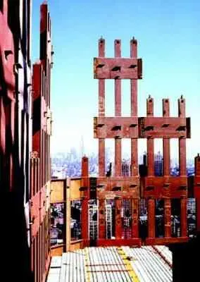
Figure 2-7 Shows the erection of prefabricated components, forming exterior wall and floor deck units.
This is a view from the North Tower, looking north toward the Empire State Building. Note the yellow and red lines in the concrete. What are these? Note, in particular, the three V-shaped features in/on the concrete, along the north wall (but not along the west wall).
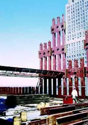
Figure 2-8 Shows the erection of floor framing during original construction.
This is another view from the North Tower (looking north west). The other high-rise is the Verizon building. Note the vertical gaps in the box columns of the perimeter wall. Gaps in the box columns do not seem to be a sensible feature in a supposedly load bearing wall. Is this because the perimeter wall was not required to carry much of the weight of the building, but was mainly a feature designed to give the WTC its required rigidity (against wind loading)? Notice the three parallel light-colored lines (about 4 inches wide) in the concrete. One also wonders why the pile of steel in the foreground was hoisted up the building, unless it was to be incorporated in the structure.
These figures illustrate this construction, and Figure 2-9 shows a cross-section through typical floor framing. Floors were designed for a uniform live load of 100 pounds per square foot (psf) over any 200-square-foor area with allowable live load reductions taken over larger areas. At building corners, this amounted to a uniform live load (unreduced) of 55 psf.
At approximately 10,000 locations in each building, viscoelastic dampers extended between the lower chords of the joists and gusset plates mounted on the exterior columns beneath the stiffened seats (Detail A in Figure 2-6). I find it really strange that dampers are attached to only one end of each truss. It doesn't make much sense to dampen vibration at one end while letting the other end «blow in the breeze». These dampers were the first application of this technology in a high-rise building, and were provided to reduce occupant perception of wind-induced building motion.
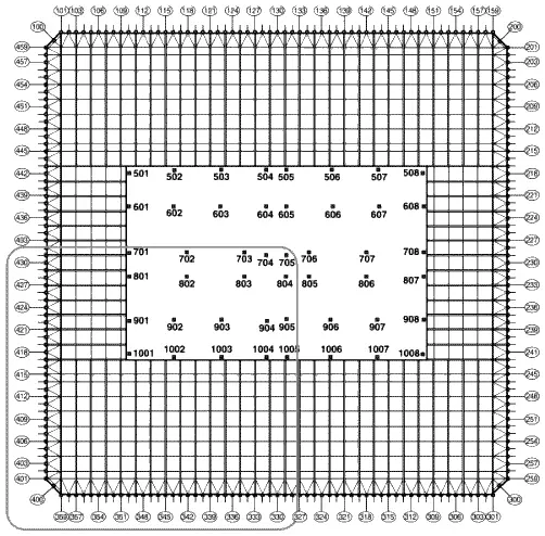
Figure 2-2 Representative structural framing plan, upper floors.
You may wish to compare the above floor plan with this one taken from Godfrey, GB (Editor); Multi-Storey Buildings in Steel, Second Edition; Collins, London, England,1985, ISBN 0 00 383031 4. The differences are quite telling.
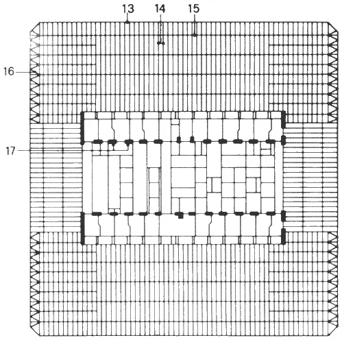
Figure 2-2-A Structural system for typical floor.
The numbers in the figure denote:
13 — Perimeter frame
14 — Bar joists 900 mm deep
15 — Secondary joists
16 — Horizontal floor bracing
17 — Core box columns
That the second floor plan is more accurate than the first, is plain from the above photo where the diagonal brace members (the V-shaped features in the diagrams) are clearly visible in the concrete along the north wall, but not along the west wall (as in the second diagram but not the first).
Pairs of flat bars extended diagonally from the exterior wall to the top chord of adjacent trusses (this is puzzling, as the top chords of the trusses are set in the concrete slab, yet one can clearly see these bars on the concrete surface in the above mentioned photo) . These diagonal flat bars, which were typically provided with shear studs, provided horizontal shear transfer between the floor slab and exterior wall, as well as out-of-plane bracing for perimeter columns not directly supporting floor trusses (Figure 2-2).
The core consisted of 5-inch concrete fill on metal deck supported by floor framing of rolled structural shapes, in turn supported by a combination of wide flange shape and box-section columns. Some of these columns were very large, with cross-sections measuring 14 inches wide by 36 inches deep. In upper stories, these rectangular box columns transitioned into heavy rolled wide flange shapes (see Appendix B for a picture of the transition from box column to H-column).
Читать дальшеИнтервал:
Закладка:
Похожие книги на «11 сентября 2001»
Представляем Вашему вниманию похожие книги на «11 сентября 2001» списком для выбора. Мы отобрали схожую по названию и смыслу литературу в надежде предоставить читателям больше вариантов отыскать новые, интересные, ещё непрочитанные произведения.


Обсуждение, отзывы о книге «11 сентября 2001» и просто собственные мнения читателей. Оставьте ваши комментарии, напишите, что Вы думаете о произведении, его смысле или главных героях. Укажите что конкретно понравилось, а что нет, и почему Вы так считаете.