Chris Binns - Introduction to Nanoscience and Nanotechnology
Здесь есть возможность читать онлайн «Chris Binns - Introduction to Nanoscience and Nanotechnology» — ознакомительный отрывок электронной книги совершенно бесплатно, а после прочтения отрывка купить полную версию. В некоторых случаях можно слушать аудио, скачать через торрент в формате fb2 и присутствует краткое содержание. Жанр: unrecognised, на английском языке. Описание произведения, (предисловие) а так же отзывы посетителей доступны на портале библиотеки ЛибКат.
- Название:Introduction to Nanoscience and Nanotechnology
- Автор:
- Жанр:
- Год:неизвестен
- ISBN:нет данных
- Рейтинг книги:4 / 5. Голосов: 2
-
Избранное:Добавить в избранное
- Отзывы:
-
Ваша оценка:
Introduction to Nanoscience and Nanotechnology: краткое содержание, описание и аннотация
Предлагаем к чтению аннотацию, описание, краткое содержание или предисловие (зависит от того, что написал сам автор книги «Introduction to Nanoscience and Nanotechnology»). Если вы не нашли необходимую информацию о книге — напишите в комментариях, мы постараемся отыскать её.
Introduction to Nanoscience and Nanotechnology — читать онлайн ознакомительный отрывок
Ниже представлен текст книги, разбитый по страницам. Система сохранения места последней прочитанной страницы, позволяет с удобством читать онлайн бесплатно книгу «Introduction to Nanoscience and Nanotechnology», без необходимости каждый раз заново искать на чём Вы остановились. Поставьте закладку, и сможете в любой момент перейти на страницу, на которой закончили чтение.
Интервал:
Закладка:
Although these measurements moved from free beam nanoparticles to those supported on a surface, they were still for isolated nanoparticles and did not show directly how to make a high moment material. Depositing an entire film of nanoparticles reduced the effect of the surface as the particles came into contact and both the orbital and spin moments converged with the bulk values. To make matters worse, films made by depositing preformed nanoparticles on a surface such as the one shown in Figure 1.10are highly porous with an atomic density around 60% that of the bulk so the magnetic field produced by such a film would be less than that generated by bulk Fe. The same set of experiments, however, also showed that coating the Fe nanoparticles with Co while they were on the surface did not remove the enhanced orbital moment, and the Fe spin moment increased even further so that a total moment of 2.6 μ B/atom was recorded for 200‐atom nanoparticles, compared to 2.2 μ B/atom in the bulk. The data from the Co‐coated nanoparticles supported on a surface are plotted on the Fe nanoparticle curve in Figure 1.9and it is observed that they show magnetic moments as high as the free nanoparticles but in a film that could be removed from its UHV environment without converting the Fe to oxide.
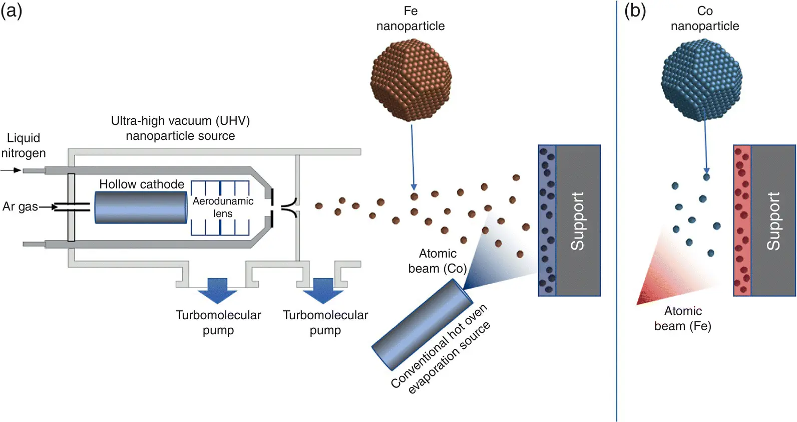
Figure 1.11 Producing nanostructured films by cluster beam deposition.Nanostructured films can be produced by depositing preformed nanoparticles from a UHV cluster source onto a substrate along with an atomic beam from a conventional hot oven evaporation source. (a) Fe nanoparticles in a Co matrix. (b) Co nanoparticles in an Fe matrix.
These experiments suggested a method to produce a thin film with a magnetization exceeding the Slater–Pauling limit, which is illustrated in Figure 1.11a. If Fe nanoparticles from a UHV nanoparticle source (see Chapter 5, Section 5.1.2) are deposited onto a surface in conjunction with an atomic beam from a conventional hot oven evaporator source, then an atomic film (matrix) containing embedded nanoparticles is created. The atoms fill all the gaps between the particles producing a film with the bulk density and each particle will retain its enhanced orbital and spin moments found in the aforementioned study. In addition, since the matrix has a very high proportion of interface atoms, it should display enhanced magnetic moments as well. Figure 1.11a shows Fe nanoparticles embedded in a Co matrix but clearly with this setup, it is straightforward to reverse the materials and produce films of Co nanoparticles in an Fe matrix as shown in Figure 1.11b.
A few years later this idea was confirmed and films with a magnetization exceeding the Slater–Pauling limit were produced [11]. The data are shown in Figure 1.12, which plots the magnetic moment per atom for Fe nanoparticles in Co matrices (red dots) and Co nanoparticles in Fe matrices (blue dots) compared to the Slater–Pauling curve for conventional Fe–Co alloys. Note that due to an accident of the units and the densities of Fe and Co, the conversion factor from magnetic moment per atom in Bohr magnetons ( μ B) to magnetic field produced in Tesla is very close to 1.0 so the two measures are often interchanged. The factors are 0.99 for Fe and 1.06 for Co so that the Co‐rich end corresponds to a slightly higher magnetic field than the value indicated in μ B/atom.
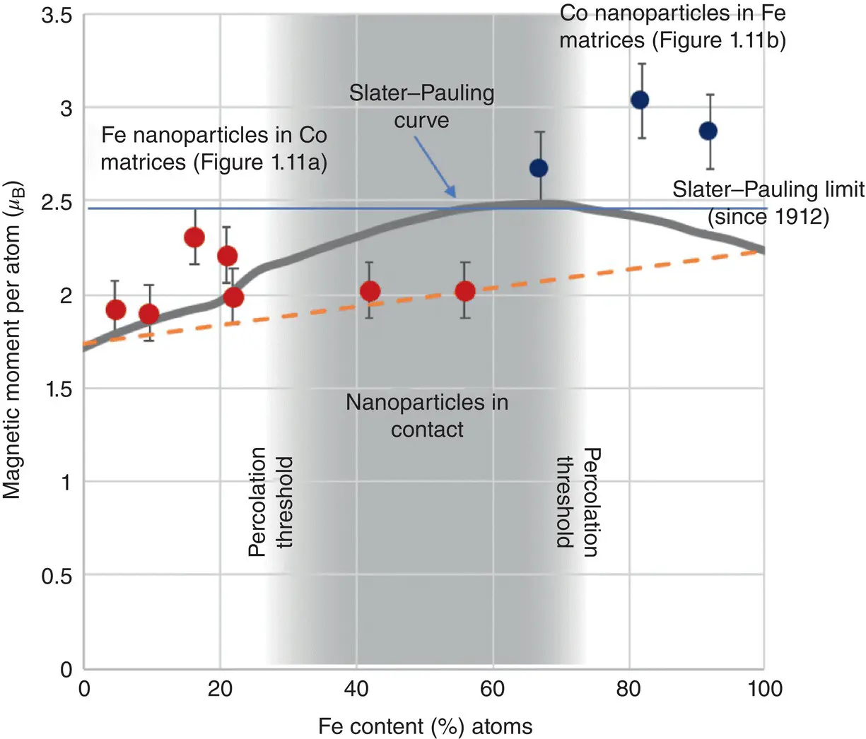
Figure 1.12 High‐moment films produced by cluster beam deposition.Magnetic moment/atom in nanoparticle‐assembled films compared to the Slater–Pauling curve.
What the data clearly show is that the magnetization in the films of Fe nanoparticles embedded in Co matrices exceeds that of the Slater–Pauling curve till the density of nanoparticles reaches the percolation threshold at 25%. Then, the magnetization reduces to a value that is the weighted average of the Fe and Co bulk magnetic moments. This is due to the nanoparticles coming into contact and the Fe–Co interface reducing so that essentially there is a phase‐separated mixture. It is evident from the data for the Co nanoparticles in an Fe matrix, however, that a saturation magnetization of about 3 T can be achieved, which is significantly higher than the Slater–Pauling limit. The data in Figure 1.12are from a material rather than isolated nanoparticles, but it is still in the form of a very thin film approximately 50 nm thick, that is, a long way from a bulk material. With big improvements in the flux from nanoparticle sources, however, there are now patented ideas to produce bulk quantities of this nanostructured alloy, which the author's group is working on at the Universidad de Castilla‐La Mancha in Spain. It is envisaged that this material will find its way into motors for all‐electric transport within eight years where it will produce at least a 20% improvement in the power to weight ratio of the motor.
This development has been labored as it is an excellent example of incremental nanotechnology moving from the lab into applications. This is just a single example and the method of producing materials shown in Figure 1.11is a supreme way of making nanostructured materials in general. One can control the grain size independently of the volume fraction, there is free choice of the material in the grains or the matrix, and it is possible, using methods shown in Chapter 5, to make the nanoparticles out of more than one material in a range of motifs. These include alloy, core‐shell, and dumbbell nanoparticles, also called Janus particles as they have two different materials exposed at the surface. The method is likely to find its way into a range of applications in advanced materials.
1.3 The Mechanical Properties of Nanostructured Materials
Mechanical properties such as the strength of metals can also be greatly improved by making them with nanoscale grains. Several basic attributes of materials are involved in defining their mechanical properties. One is strength, which includes characteristics with more precise definitions but basically determines how much a material deforms in response to a force. Others are hardness, which is given by the amount another body such as a ball bearing or diamond is able to penetrate a material, and wear resistance, which is determined by the rate at which a material erodes when in contact with another. These properties are dominated by the grain structure found in metals produced by normal processing. An example of the grains structure of a “normal” piece of metal is shown in Figure 1.13a, which is an electron microscope image showing the grain structure of tin. Each grain is a single‐crystal with a typical size of about 20 μm (20 000 nm). The mechanical properties listed above are due to grains slipping past each other or deforming, so clearly what happens at the grain boundaries is very important in determining properties such as strength, etc. It is possible by various techniques including nanoparticle deposition ( Figure 1.11), electro‐deposition, and special low‐temperature milling methods to produce metal samples in which the grains are a few nanometers across. An example is shown in Figure 1.13b, where, on the same scale as Figure 1.13a, the grain structure disappears to show a homogenous material. Blowing up the magnification a further 15 000×, however, ( Figure 1.13c) reveals the new nanoscale grain structure. In this image, the individual planes of atoms are indicated by the sets of parallel lines and the boundaries are where the lines suddenly change direction as highlighted for one of the grains. Whereas in the coarse‐grained metal shown in Figure 1.13a, about one atom in 100 000 is at a grain boundary, in the nano‐grained equivalent, about a quarter of the atoms are at a grain boundary. Clearly, this change is going to have a marked effect on the mechanical properties of the material. Changes in mechanical properties with grain size were quantified over 50 years ago by Hall and Petch [12, 13], but the modern ability to control the grain size right down to the nanometer scale can produce significant increases in performance.
Читать дальшеИнтервал:
Закладка:
Похожие книги на «Introduction to Nanoscience and Nanotechnology»
Представляем Вашему вниманию похожие книги на «Introduction to Nanoscience and Nanotechnology» списком для выбора. Мы отобрали схожую по названию и смыслу литературу в надежде предоставить читателям больше вариантов отыскать новые, интересные, ещё непрочитанные произведения.


Обсуждение, отзывы о книге «Introduction to Nanoscience and Nanotechnology» и просто собственные мнения читателей. Оставьте ваши комментарии, напишите, что Вы думаете о произведении, его смысле или главных героях. Укажите что конкретно понравилось, а что нет, и почему Вы так считаете.