Maan H. Jawad - Fabrication of Metallic Pressure Vessels
Здесь есть возможность читать онлайн «Maan H. Jawad - Fabrication of Metallic Pressure Vessels» — ознакомительный отрывок электронной книги совершенно бесплатно, а после прочтения отрывка купить полную версию. В некоторых случаях можно слушать аудио, скачать через торрент в формате fb2 и присутствует краткое содержание. Жанр: unrecognised, на английском языке. Описание произведения, (предисловие) а так же отзывы посетителей доступны на портале библиотеки ЛибКат.
- Название:Fabrication of Metallic Pressure Vessels
- Автор:
- Жанр:
- Год:неизвестен
- ISBN:нет данных
- Рейтинг книги:4 / 5. Голосов: 1
-
Избранное:Добавить в избранное
- Отзывы:
-
Ваша оценка:
Fabrication of Metallic Pressure Vessels: краткое содержание, описание и аннотация
Предлагаем к чтению аннотацию, описание, краткое содержание или предисловие (зависит от того, что написал сам автор книги «Fabrication of Metallic Pressure Vessels»). Если вы не нашли необходимую информацию о книге — напишите в комментариях, мы постараемся отыскать её.
A comprehensive guide to processes and topics in pressure vessel fabrication Fabrication of Metallic Pressure Vessels
Fabrication of Metallic Pressure Vessels
Fabrication of Metallic Pressure Vessels — читать онлайн ознакомительный отрывок
Ниже представлен текст книги, разбитый по страницам. Система сохранения места последней прочитанной страницы, позволяет с удобством читать онлайн бесплатно книгу «Fabrication of Metallic Pressure Vessels», без необходимости каждый раз заново искать на чём Вы остановились. Поставьте закладку, и сможете в любой момент перейти на страницу, на которой закончили чтение.
Интервал:
Закладка:
When nozzles beyond a certain size penetrate a vessel wall, reinforcement is required to take the pressure loads that would otherwise have been transmitted through the material cut from the shell or head for placement of the nozzle. The ASME code puts limits on what material may be counted as contributing to this load carrying capability. Simple area replacement is typically used, provided that the reinforcing material is of strength equal to or greater than that of the material it is replacing. There are numerous ways of providing this material. Because the code allows essentially any material within a certain distance to be counted, any excess material in the shell itself, the nozzle wall, the weld, added reinforcing pads, or shell inserts, may be considered.
The best means of providing reinforcing beyond that inherent in the design is often fairly obvious, but in some cases a cost estimate for more than one approach may be needed to evaluate the trade‐off.
If a vessel has a limited number of penetrations requiring reinforcement, accepting the labor and material cost of providing reinforcement on a few nozzles may be inexpensive compared to providing a heavier shell that results in an integrally reinforced design. When a vessel has many nozzle penetrations requiring reinforcement, however, the labor associated with providing that reinforcement may far exceed the additional cost of a heavier shell wall and thicker shell and nozzle to shell welds. If most or all of the nozzles requiring reinforcement are located in the same area, it may make sense to make one shell course thicker than the others to provide integral reinforcement.
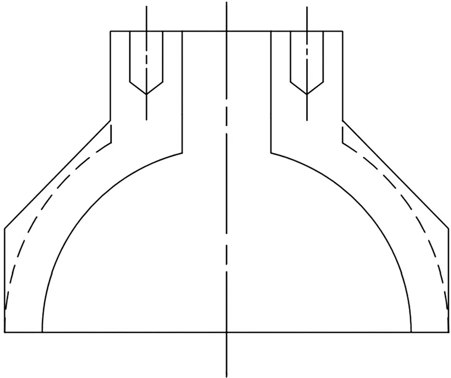
Figure 1.1 Outside machining of a hemispherical head
Another way of providing additional nozzle reinforcement when a flanged nozzle is required is the use of LWN flanges. If the nozzle protrusion is not excessive, then unless the cost of labor is extremely low or the cost of material extremely high (e.g., high nickel materials for their corrosion resistance or high temperature strength), it will almost always be more economical to use an LWN flange than to add a reinforcing pad. The neck of an LWN flange normally has an outside diameter equal to the hub diameter of a slip‐on flange, and it may be ordered in a variety of lengths. Thus, particularly if it is acceptable to allow the nozzle to protrude into the vessel, an LWN flange can almost always fulfill the need for additional reinforcement. While the cost of an LWN flange is significantly greater than that of either a slip‐on or a welding neck flange, it has the advantage of eliminating the following costs: flange to nozzle weld, reinforcing (or insert) plate, reinforcing or insert plate layout, forming of reinforcing plate, drilling and tapping of reinforcing plate vent hole, fit up of reinforcing plate, and welding of reinforcing plate both to the shell and to the nozzle.
1.3.2.6 Enhanced inspection for higher joint efficiency
Enhanced inspection to increase joint efficiency can result in a significant reduction in wall thickness on a heavy wall vessel. This, in some cases, sufficiently reduces the wall thickness to allow the use of the next smaller stock thickness, thereby reducing material and other fabrication costs. When inspection has not been performed to allow 100% joint efficiency of shell longitudinal or head welds, however, then locating shell longitudinal or head welds so that welds aren’t included in zones used for reinforcement may, in some cases, be enough to eliminate the need for extra reinforcement, since the excess material in the shell can be counted based on the 100% joint efficiency of the parent material.
Major considerations in deciding whether to perform inspections to reduce other costs include the cost of the inspection, the anticipated labor and material cost savings, and the level of confidence that the welds will pass inspection the first time. If inspection shows that weld repairs are required, all savings in labor and material may be wiped out by the cost of repairs and reinspection, resulting in no benefit to the fabricator and a loss in terms of schedule, and tolerances may be affected as well.
Example 1.1
This example illustrates an actual vessel for which the design approach eliminated a large number of operations as well as fabrication risk by using a much heavier wall than originally specified.
The heavy wall vessel shown in Figure 1.2is 16 ft long, 30 in. diameter, 4 in. nominal wall, with flat bolted heads, 88 total penetrations, and the full shell length machined inside. Figure 1.3shows the side views of the same vessel. The vessel might have been fabricated of much thinner material, but was fabricated this way to reduce cost.
The vessel was originally designed using a 1‐3/4 in. thick shell with a number of heavier shell plate inserts with blind drilled and tapped holes for attaching instrumentation. The original design also had an added heavy section at each end with drilled and tapped holes for installation of cover flanges. The fabricator evaluated four approaches before making a proposal. Each approach included the large nozzles welded into fabricated shell sections. The four approaches were (1) as designed originally; (2) a centrifugal casting with flats machined and drilled and tapped for small penetrations, with the internal surface machined after insertion of the large nozzles so as to meet internal tolerance requirements; (3) a single piece, trepanned, heavy forged cylinder with the same approach as (2) for nozzle penetrations, and (4) a rolled and welded heavy plate wall shell with the same approach as (2) for nozzle penetrations.
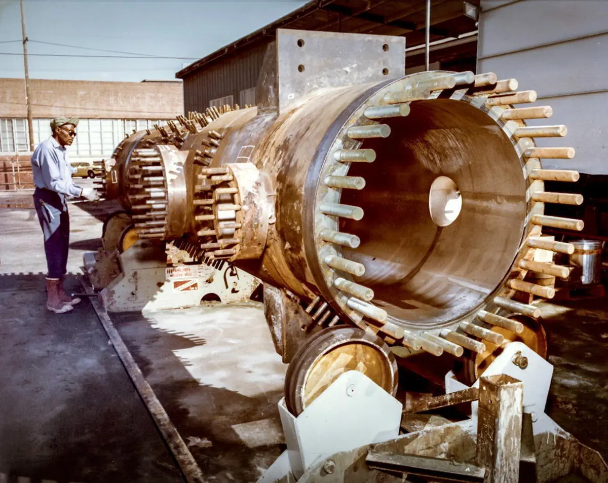
Figure 1.2 A vessel fabricated with a heavy wall to minimize cost
( Source: Los Alamos National Laboratory)
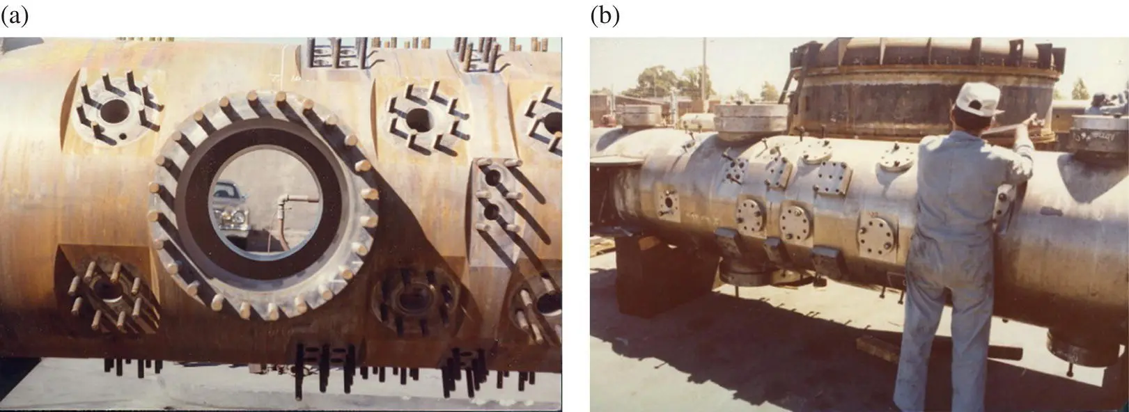
Figure 1.3 Side views of the vessel in Figure 1.2
The rolled and welded design proved to be the least costly. All of the heavy walled designs eliminated two circumferential welds at the ends, as well as the cost of layout and cutting of holes, and welding in the plates for the small openings. They also reduced the risk of distortion by minimizing the amount of welding required. The centrifugal cast and forged designs had higher costs for the basic cylinder than did the rolled and welded design.
When the user recognized the costs and the tolerance risks associated with welding a large number of nozzle plates, the rolled and welded design was accepted. The rolled and welded shell was produced by a pipe fabricating shop, helping to manage costs.
1.3.2.7 Process choices
Often decisions about cost of fabrication depend on the quantity of product being produced. Vessels will be more economical to produce if processes are optimized, but sometimes the cost of optimization is not warranted. For a single vessel, or even a small number of vessels, the cost of procuring forming equipment and optimal welding equipment and costs of developing tooling will likely exceed any profit on the job. Sometimes even setting up existing tooling for a vessel will not pay for itself, and it will be less expensive to fabricate the product using less efficient means but with essentially no initial setup cost.
Читать дальшеИнтервал:
Закладка:
Похожие книги на «Fabrication of Metallic Pressure Vessels»
Представляем Вашему вниманию похожие книги на «Fabrication of Metallic Pressure Vessels» списком для выбора. Мы отобрали схожую по названию и смыслу литературу в надежде предоставить читателям больше вариантов отыскать новые, интересные, ещё непрочитанные произведения.


Обсуждение, отзывы о книге «Fabrication of Metallic Pressure Vessels» и просто собственные мнения читателей. Оставьте ваши комментарии, напишите, что Вы думаете о произведении, его смысле или главных героях. Укажите что конкретно понравилось, а что нет, и почему Вы так считаете.