John Crisp - Introduction to Microprocessors and Microcontrollers
Здесь есть возможность читать онлайн «John Crisp - Introduction to Microprocessors and Microcontrollers» весь текст электронной книги совершенно бесплатно (целиком полную версию без сокращений). В некоторых случаях можно слушать аудио, скачать через торрент в формате fb2 и присутствует краткое содержание. Год выпуска: 2004, ISBN: 2004, Издательство: Elsevier, Жанр: Компьютерное железо, на английском языке. Описание произведения, (предисловие) а так же отзывы посетителей доступны на портале библиотеки ЛибКат.
- Название:Introduction to Microprocessors and Microcontrollers
- Автор:
- Издательство:Elsevier
- Жанр:
- Год:2004
- ISBN:0-7506-5989-0
- Рейтинг книги:3 / 5. Голосов: 1
-
Избранное:Добавить в избранное
- Отзывы:
-
Ваша оценка:
Introduction to Microprocessors and Microcontrollers: краткое содержание, описание и аннотация
Предлагаем к чтению аннотацию, описание, краткое содержание или предисловие (зависит от того, что написал сам автор книги «Introduction to Microprocessors and Microcontrollers»). Если вы не нашли необходимую информацию о книге — напишите в комментариях, мы постараемся отыскать её.
Introduction to Microprocessors and Microcontrollers — читать онлайн бесплатно полную книгу (весь текст) целиком
Ниже представлен текст книги, разбитый по страницам. Система сохранения места последней прочитанной страницы, позволяет с удобством читать онлайн бесплатно книгу «Introduction to Microprocessors and Microcontrollers», без необходимости каждый раз заново искать на чём Вы остановились. Поставьте закладку, и сможете в любой момент перейти на страницу, на которой закончили чтение.
Интервал:
Закладка:
Carry flag (C) and the half-carry flag (H)
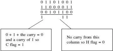
When addition is carried out, it sometimes results in a bit being carried over to the next column. The C flag copies the value of the carry from bit 7 and the H flag records the carry from bit 3 into bit 4 during additions. It also reflects the value of the ‘borrow’ in subtractions.
Here is an example of an addition showing the C and H flags.
Parity/overflow flag (P/V)
This is used for two separate purposes.
The ‘V’ in the title refers to oVerflow in arithmetic calculations. Some combinations of numbers can be misinterpreted and give an apparently incorrect answer, as we will see.
When the flag spots a possible error it is set, when no error is likely, it is cleared.
Here is an example where we could see a problem.
We are going to add two positive numbers +96 and +66 so even if we can’t guess the result, we do at least know that it is a positive number.
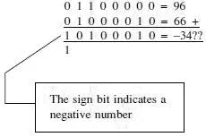
In this example, we have added two numbers that start with zero and are therefore positive and the result starts with a one, which is a negative number so the P/V flag will be set.
An easy way to check for a possible error is to look at the carry into bit 7 and the carry out of bit 7.
The rule is:
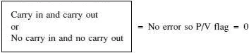
In our example, there was a 1 carried into bit 7 from the previous column but there was no bit carried out from bit 7. This does not fit into the rule above so the P/V flag will be set to 1 indicating a possible error in the result.
Its second purpose is to operate in its parity mode.
In this mode, it checks a byte of data and counts the number of 1 states, if the total is an even number, the P/V flag is set and if odd, it is cleared.
So the byte 10110101 would mean P/V=0 since the number 1 occurs 5 times, which is an odd number. And 10010110 would result in P/V=1 because there are four occasions when the number 1 occurs and 4 is an even number.
This flag operates in the P or V mode depending on the instruction being carried out at the time.
We will look at parity in more detail in Chapter 17.
The general-purpose registers
The general-purpose registers are all 8-bit registers but if we like, we can use them two at a time as 16-bit registers. When pairing them up, our choice is restricted to the way suggested by Figure 8.2. We can combine BC, DE or HL but it’s not a free choice, we cannot choose any two such as B and L. We can use a pair like BC as a 16-bit register and, at the same time, use D/E/H/L as separate 8-bit registers. As usual, the alternate register set behaves in exactly the same manner.
They have labelled the first four as B, C, D and E, so it may seem a little odd to use H and L for the last two.
The reason for this is that these registers are also used to keep track of memory addresses. The Z8018X has a 16-bit address bus and so requires a 16-bit register to be able to store a full address. The H and L stand for High and Low bytes of the address so if we wanted to store the address 2684H, we would put 84 in the L register and 26 in the H register, using binary of course. As well as being used to hold an address, the H and L registers can still be used for any other purpose that we want, just like B,C, D and E.
Special-purpose registers
Program counter (PC)
A program is a list of instructions for the microprocessor to carry out. Before use, they must be stored in some ROM or RAM. Let’s assume that we used addresses starting from 6400H. To run the program we must tell the microprocessor to ‘go’ from 6400H. What we are actually doing is loading the address 6400H into the program counter and the microprocessor starts from there. Once it has completed the instruction in 6400H, it goes to the next address 6401H and then 6402H etc until it reaches the end of the program. The purpose of the program counter is to keep track of the address that is going to be used next.
Stack pointer (SP)
If someone gave us a telephone number to remember, we would be likely to reach for a scrap of paper and a pencil to write it down. Our note may look like Figure 8.4.
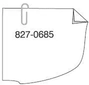
Figure 8.4 A number to remember
If we were then given another couple of numbers, we are likely to jot them down, in order, under the first one as in Figure 8.5.
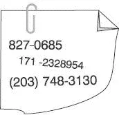
Figure 8.5 A few more numbers
We could read them back in order by reading the bottom one first, then the next and finally the top one. The first one to be entered was the last one to come out.
The microprocessor could do something similar by storing information in a series of 16-bit memory locations called a ‘stack’. The stack is loaded in order and then unloaded starting from the last number stored and working back to the top of the stack. The first number that was stored would be retrieved last and for this reason it would be called a ‘first-in, last-out’ method or FILO. For maximum confusion, this can also be called a LIFO system that, of course, means exactly the same. Have a think about it.
Inside the microprocessor, a series of RAM locations are reserved to be used as a stack and an address counter must be employed to keep track of what address of the stack is to be used next. This counter is called a stack pointer since it ‘points at’ the next address to be used.
The stack is generally used by the microprocessor to store data on a very temporary basis. We are allowed to use it but the microprocessor takes priority and doesn’t know that we have been fiddling with it. For example, if the microprocessor had stored three bits of data in order as in Figure 8.6(a) and we put one piece of our data on the end as in Figure 8.6(b), there would now be data in four locations. However, the microprocessor would not be aware of this. When the microprocessor wished to retrieve its data, it would unload three bytes and accidentally get the wrong one as in Figure 8.6(c).
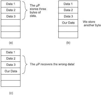
Figure 8.6 Using the stack
The moral of this story is leave the stack alone – or be very careful! The technical data will always give you sufficient information to be able to know whether or not the microprocessor will be using the stack but it still takes a lot of working through to be sure.
Index registers
We have two index registers, one called X and the other called Y. They both perform the same function.
An index is used in situations in which we wish to perform a sequence of similar tasks one after the other. Perhaps to use data stored in a series of memory locations. The 16-bit content of the index register can be added to the contents of the program counter (PC) to produce a new address.
As an example, let’s assume that we are running a program which after using address 2600H we would like it to use some data stored in address 3800H. We could do this by loading the 16-bit number 1200H into the X register and instruct the microprocessor to go to the address written as PC+IX (program counter and index X). In this case, the microprocessor goes to address 2600H+1200H=3800H to retrieve the data to be used. This jump from 2600H to 3800H is called an offset or we may say that the index X register has provided an offset of 1200H. In this example, index register Y could have been used equally well.
Читать дальшеИнтервал:
Закладка:
Похожие книги на «Introduction to Microprocessors and Microcontrollers»
Представляем Вашему вниманию похожие книги на «Introduction to Microprocessors and Microcontrollers» списком для выбора. Мы отобрали схожую по названию и смыслу литературу в надежде предоставить читателям больше вариантов отыскать новые, интересные, ещё непрочитанные произведения.


Обсуждение, отзывы о книге «Introduction to Microprocessors and Microcontrollers» и просто собственные мнения читателей. Оставьте ваши комментарии, напишите, что Вы думаете о произведении, его смысле или главных героях. Укажите что конкретно понравилось, а что нет, и почему Вы так считаете.